Sponsored

Winch install: Project Overkill

OP
OP

YBABRAT

Well-Known Member
Joined
May 12, 2024
Threads
55
Messages
1,409
Reaction score
1,355
Location
VIRGINIA
Vehicle(s)
2019 2 Door Rubicon X Wannabe
Occupation
None... but it pays well.
I'm thinking a fuse at the battery to prevent melting the red cable might not be a bad idea. A very smart industrial electrician once told me the fuse protects the wire. Just a thought. You certainly seem to know what you're doing.
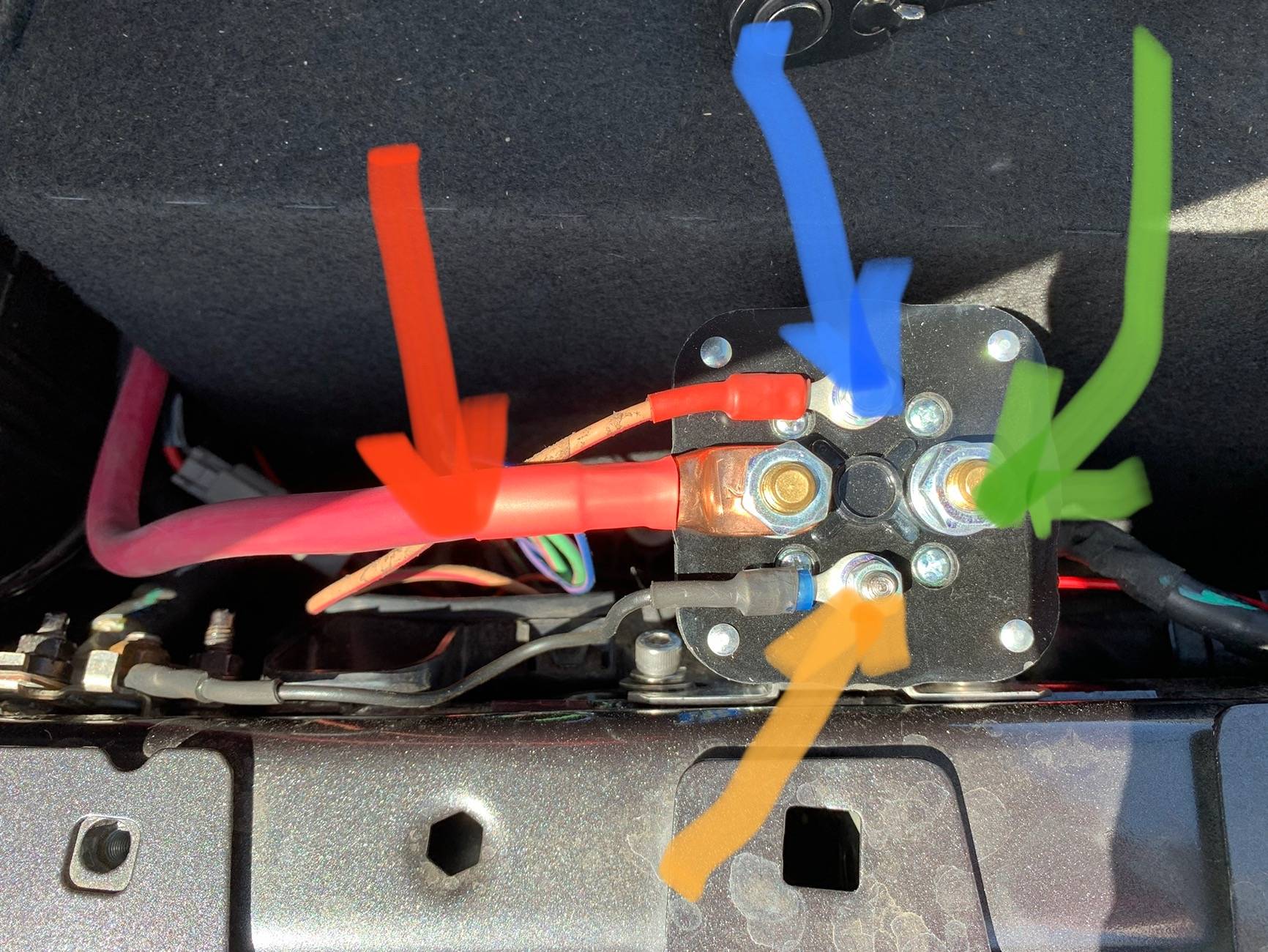
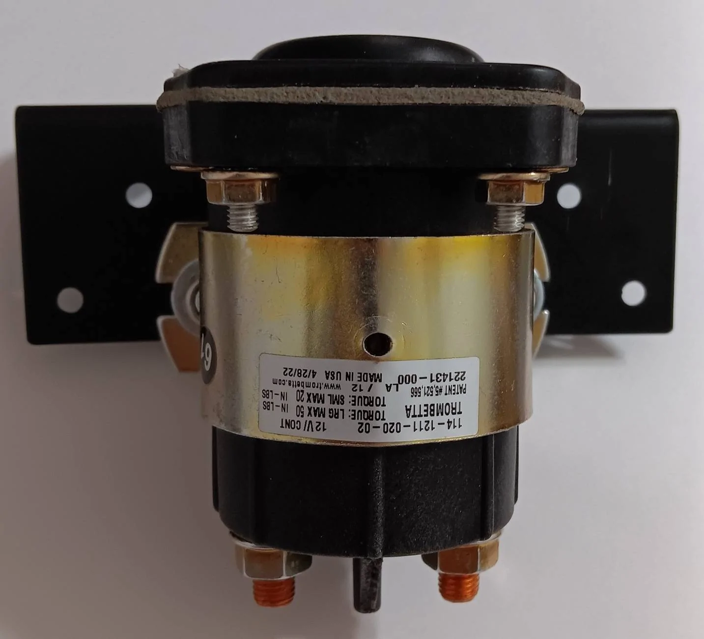
The circuit has multiple fail safes. The type of solenoid, shown within the first page pictures, has contact studs isolated. Mounting it upside down has no protrusions to make contact with ground.

The short length of 0/1 cable will never over heat, due to its length, making internal resistance super low.

The longer cable going to the winch will be shorter than given by WARN, and of larger gauge. There should not be any issue passing 400A. But that will be short duration. By the time 360A is drawn by the winches operation, the monitor will see a voltage drop that will disengage the solenoid. Either the winch heated up or alternator was near overload state. Thus a reason to have a smart disconnect.

Second fail safe... the monitor will not attempt to switch back power until battery or charging system returns back to 100%... then will count down 16 minutes before activating solenoid. See my picture of partial installation. Before winching, you set the battery / charging system voltage. From there it detects voltage state under current draw.

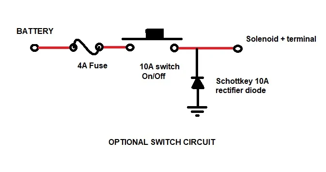
3rd fail safe is Aux power. All are already fused. No need to add another fuse for switching solenoid.

4th fail safe is ignition switch... if using my parameters on aux settings, ignition will disconnect power. The monitor controller will only activate when the aux switch is used.

5th fail safe... the monitor controller has an off setting and will remain off until set on. This feature overrides its function. Even though it is powered on with Aux switch you can turn off the solenoid manually if active.
Sponsored

 
OP
OP

YBABRAT

Well-Known Member
Joined
May 12, 2024
Threads
55
Messages
1,409
Reaction score
1,355
Location
VIRGINIA
Vehicle(s)
2019 2 Door Rubicon X Wannabe
Occupation
None... but it pays well.
Your circuit diagram shows a battery connection to the Aux Switch positive wire, making that wire hot (and unfused) into the PDC when the Optional Switch and XY-CD63 are closed with the Aux Switch off.
The optional switch is basically to override a bad XY-CD63. It is wired to only connect aux switch voltage. If you add an optional switch to override when the XY-CD63 is fully functional... the feed back into the system you speak of does not happen... it would be like two wires being used together, even if the XY-CD63 goes bad, the voltage can't go past the relay that is inside the XY-CD63. Its relay output is a normally open connection, so it is disconnected by function.
 

Jtphoto

Well-Known Member
First Name
Jeff
Joined
Dec 10, 2017
Threads
23
Messages
3,007
Reaction score
3,499
Location
Thunder Bay ON
Vehicle(s)
2022 Rubicon Xtreme Recon Granite Crystal
I used a Stinger solenoid powered by my factory Aux1 switch.
Jeep Wrangler JL Winch install: Project Overkill IMG_7729
 
OP
OP

YBABRAT

Well-Known Member
Joined
May 12, 2024
Threads
55
Messages
1,409
Reaction score
1,355
Location
VIRGINIA
Vehicle(s)
2019 2 Door Rubicon X Wannabe
Occupation
None... but it pays well.
From what I can tell, the XY-CD63 can take power from the battery if the Optional Switch is closed, and would close the relay if the battery/system voltage is within your parameters. That would make the Aux Switch wire hot and unfused into the PDC even when the Aux Switch is off.
Nope... can't happen. It's isolated by function. I dismantled and removed the relay to modify, and changed my mind, once I realized many would not bother. Instead I worked with simple connections, knowing how the XY-CD63 operates or should I say passes voltage to the solenoid.

Like I stated the XY-CD63 output is normally open relay with no provision to send voltage to the aux switch relay when off or disabled. Also the aux relay voltage should be the same as battery voltage. If aux switch is off, aux relay output is off like a switch. Voltage going to it is stopped by its function. Relays can not pass voltage when off as the connection has no contact until on. Even if on the voltage has no path to go other than the solenoid.
 
OP
OP

YBABRAT

Well-Known Member
Joined
May 12, 2024
Threads
55
Messages
1,409
Reaction score
1,355
Location
VIRGINIA
Vehicle(s)
2019 2 Door Rubicon X Wannabe
Occupation
None... but it pays well.
I used a Stinger solenoid powered by my factory Aux1 switch.
IMG_7729.jpeg
Yep, it was my choice, until I found mine in surplus. You may find my circuit a nice option if you find a benefit for your use. You have practically done most of the work already.
 

Sponsored

OP
OP

YBABRAT

Well-Known Member
Joined
May 12, 2024
Threads
55
Messages
1,409
Reaction score
1,355
Location
VIRGINIA
Vehicle(s)
2019 2 Door Rubicon X Wannabe
Occupation
None... but it pays well.
Doesn't the XY-CD63 work in both directions? Your diagram shows power potentially connected on either side.
Depends on mode. I strictly set it for discharge. Once set to discharge, you cannot change it by accident. The nomenclature is vague on input and output. In discharge mode it acts like a light switch to a load. Battery voltage in and it is switched to the output. It basically is a trap door for aux switch to activate solenoid. If voltage drops too much, it slams the door shut.

Gosh... I just realized the discussion going in circles about optional switch. I assumed it would be used as a bypass. No need to use aux switch just flip the switch. When I mean the XY-CD63 is dead, I mean no reason turn on aux switch or leave it on for bypass use.
 

Flip

Well-Known Member
First Name
Johnny
Joined
Mar 25, 2023
Threads
137
Messages
6,379
Reaction score
12,797
Location
Virginia
Vehicle(s)
2023 Jeep Wrangler Sport
Build Thread
Link
Occupation
Retired Power Plant Engineer
But that is not what was given as example. It don't pertain to this thread.
Well sure it does. The way I have it installed now is basic and simple but if someone were to wire it without a fuse or switch making it even more simple it would certainly work.
 

THAW

Well-Known Member
First Name
Foster
Joined
Oct 28, 2022
Threads
4
Messages
2,211
Reaction score
3,043
Location
PNW - prefer Middle of Nowhere
Vehicle(s)
23 JL4DrRubicon
Depends on mode. I strictly set it for discharge. Once set to discharge, you cannot change it by accident. The nomenclature is vague on input and output. In discharge mode it acts like a light switch to a load. Battery voltage in and it is switched to the output. It basically is a trap door for aux switch to activate solenoid. If voltage drops too much, it slams the door shut.

Gosh... I just realized the discussion going in circles about optional switch. I assumed it would be used as a bypass. No need to use aux switch just flip the switch. When I mean the XY-CD63 is dead, I mean no reason turn on aux switch or leave it on for bypass use.
If it's an electronic setting, it's still advisable to have physical protection in the form of a diode and/or fuse.
 
OP
OP

YBABRAT

Well-Known Member
Joined
May 12, 2024
Threads
55
Messages
1,409
Reaction score
1,355
Location
VIRGINIA
Vehicle(s)
2019 2 Door Rubicon X Wannabe
Occupation
None... but it pays well.
If it's an electronic setting, it's still advisable to have physical protection in the form of a diode and/or fuse.
Jeep Wrangler JL Winch install: Project Overkill 1000039495
 
OP
OP

YBABRAT

Well-Known Member
Joined
May 12, 2024
Threads
55
Messages
1,409
Reaction score
1,355
Location
VIRGINIA
Vehicle(s)
2019 2 Door Rubicon X Wannabe
Occupation
None... but it pays well.
I just so happened to have a few angled brackets. Oversized the holes to mount the solenoid. I do believe the fasteners i used are 8mm thread size.

May need to trim off the top bracket depth... won't know until I mount. Looking at using existing holes on upper fender frame. Blind rivets should work.

Jeep Wrangler JL Winch install: Project Overkill 1000039500
 
Last edited:

Sponsored

OP
OP

YBABRAT

Well-Known Member
Joined
May 12, 2024
Threads
55
Messages
1,409
Reaction score
1,355
Location
VIRGINIA
Vehicle(s)
2019 2 Door Rubicon X Wannabe
Occupation
None... but it pays well.
Fuse looks good.

I'm not sure what you're trying to do with the ground and diode. My diode suggestion is for the Aux Switch - it should sit somewhere on the positive wire between the Aux Switch and the Solenoid/Optional Switch junction.
Diode is for flyback from solenoid when power is removed. Any solenoid or motor will create inductance charge and try to keep electron flow. The diode is fast acting, so transient voltage spike is quickly snubbed. Not needed if optional switch circuit is the only connection to solenoid. I added the diode thinking you were keen on such issue, when in previous discussion.

To be honest the optional switch was not intended to be a primary function. More like an emergency switch if something goes wrong with the voltage sensor controller when needed.

It would be an extremely rare thing to have a solenoid coil short out when failing. They usually overheat and burn into an open circuit. The coil windings are much smaller than the wire used to power the solenoid. Thus I consider such a thing a built in fuse. Prolly faster than an automotive fuse.
 
OP
OP

YBABRAT

Well-Known Member
Joined
May 12, 2024
Threads
55
Messages
1,409
Reaction score
1,355
Location
VIRGINIA
Vehicle(s)
2019 2 Door Rubicon X Wannabe
Occupation
None... but it pays well.
The diode has nothing to do with the solenoid state or being keen.

Again, your diagram shows a battery on both sides of the XY-CD63 - that's the reason for the diode. You should avoid connecting the factory Aux Switch wire to a potential power source, but if you do use a diode.
I don't see it that way. The XY-CD63 does not produce power, it directs it. Have you read an instruction sheet or watched a video on it? The only way it can produce power is when you connect an external power source to the input, which the circuit is not doing. It's a smart switch that acts sort of like a circuit breaker. In stead of tripping on current it trips on voltage. To sample live voltage readings accurately the internal resistance is in the mega ohms. As for input and output they are the same when enabled. Only when voltage is below set limit output is off.

I really don't see how this passive device will be an issue, when there are many aftermarket addons without diodes and fuses, that have much higher wattage. Even jeep has protection for the aux switch setup. If you blow an aux fuse, then it's how you wired my design.
 
OP
OP

YBABRAT

Well-Known Member
Joined
May 12, 2024
Threads
55
Messages
1,409
Reaction score
1,355
Location
VIRGINIA
Vehicle(s)
2019 2 Door Rubicon X Wannabe
Occupation
None... but it pays well.
Yes, battery voltage on both sides... that is what a switch does. When the XY-CD63 is off or disabled by low voltage trip point, voltage at output is disabled. It us a dead open circuit. No chance voltage will pass. Even if it does, it is the equivalent of two ends of same wire connected to a power source. No current draw no path to go to, doubly so when aux switch relay is not on. I have tried to explain the optional switch is to be used as an emergency when the voltage sensing controller is bad and aux switch is off. You seem to be placing the optional switch as primary which will override my circuits functional design.
 
OP
OP

YBABRAT

Well-Known Member
Joined
May 12, 2024
Threads
55
Messages
1,409
Reaction score
1,355
Location
VIRGINIA
Vehicle(s)
2019 2 Door Rubicon X Wannabe
Occupation
None... but it pays well.
Here is an online explanation as to why... notice the diode in my circuit. It blocks 12v system from ground, not to make a short to ground. I could add one from the XY-CD63 output, but it would make it difficukt on average user to adjust properly. It is not required as it is low current isolated by relay. Impossible to feed back.

https://blog.programmablepower.com/...m,the positive output and the anode to return.
Sponsored


Top