chevymitchell
Well-Known Member
- First Name
- Shawn
- Joined
- Feb 18, 2018
- Threads
- 112
- Messages
- 5,017
- Reaction score
- 12,147
- Location
- Pueblo West, CO
- Vehicle(s)
- 2022 392XR, 2025 Wagoneer S, 2006 LJ 6-spd
- Occupation
- Avi Engineer
- Thread starter
- #1
Good evening everyone.
I took the time today to run through the potting of my locker sensors. This seems to be a very frustrating point of failure for all of us. I have experienced it myself.
Here are the DIY steps you can follow to properly pot the sensors.
**Keep in mind the amount of time required for the potting material to cure. Tacky at 3-5 hours. 24 hour full cure. Best to do both sensors at the same time when you can wait, at least, overnight.
Also, please understand that this is a temporary fix to an issue we all hope FCA is going to remedy. Hopefully there is, at a minimum, a part number for this sensor we can order through Dealers and Distributors**
Jeep JL TQ Specs: https://www.jlwranglerforums.com/complete-torque-values-for-jeep-jl-wrangler/
Tools Required:
These steps are the same for the Front and Rear Axles.


I took the time today to run through the potting of my locker sensors. This seems to be a very frustrating point of failure for all of us. I have experienced it myself.
Here are the DIY steps you can follow to properly pot the sensors.
**Keep in mind the amount of time required for the potting material to cure. Tacky at 3-5 hours. 24 hour full cure. Best to do both sensors at the same time when you can wait, at least, overnight.
Also, please understand that this is a temporary fix to an issue we all hope FCA is going to remedy. Hopefully there is, at a minimum, a part number for this sensor we can order through Dealers and Distributors**
Jeep JL TQ Specs: https://www.jlwranglerforums.com/complete-torque-values-for-jeep-jl-wrangler/
Tools Required:
- 1/4" Ratchet
- 1/4" Drive T20 Bit
- 3/8" Drive Ratchet
- 3/8" Drive 10mm
- 1/2" Drive Ratchet
- 1/2" Drive 15mm
- Drill
- 3/32" Drill Bit
- Flathead Screwdriver
- Drain Pan
- Teflon Tape
- Electrical Tape
- Sharpe/Marker
- Acetone (Optional)
- Red Loctite
- Dielectric Grease
- Shop towels or Microfiber Cloth
- 832HD Potting Compound (25mL)
These steps are the same for the Front and Rear Axles.
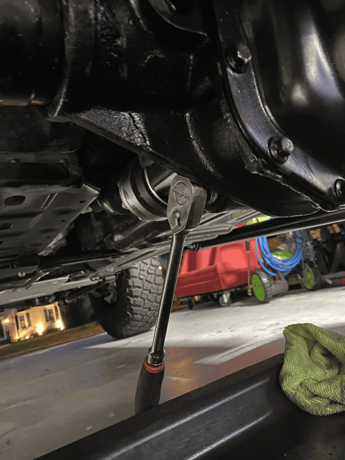
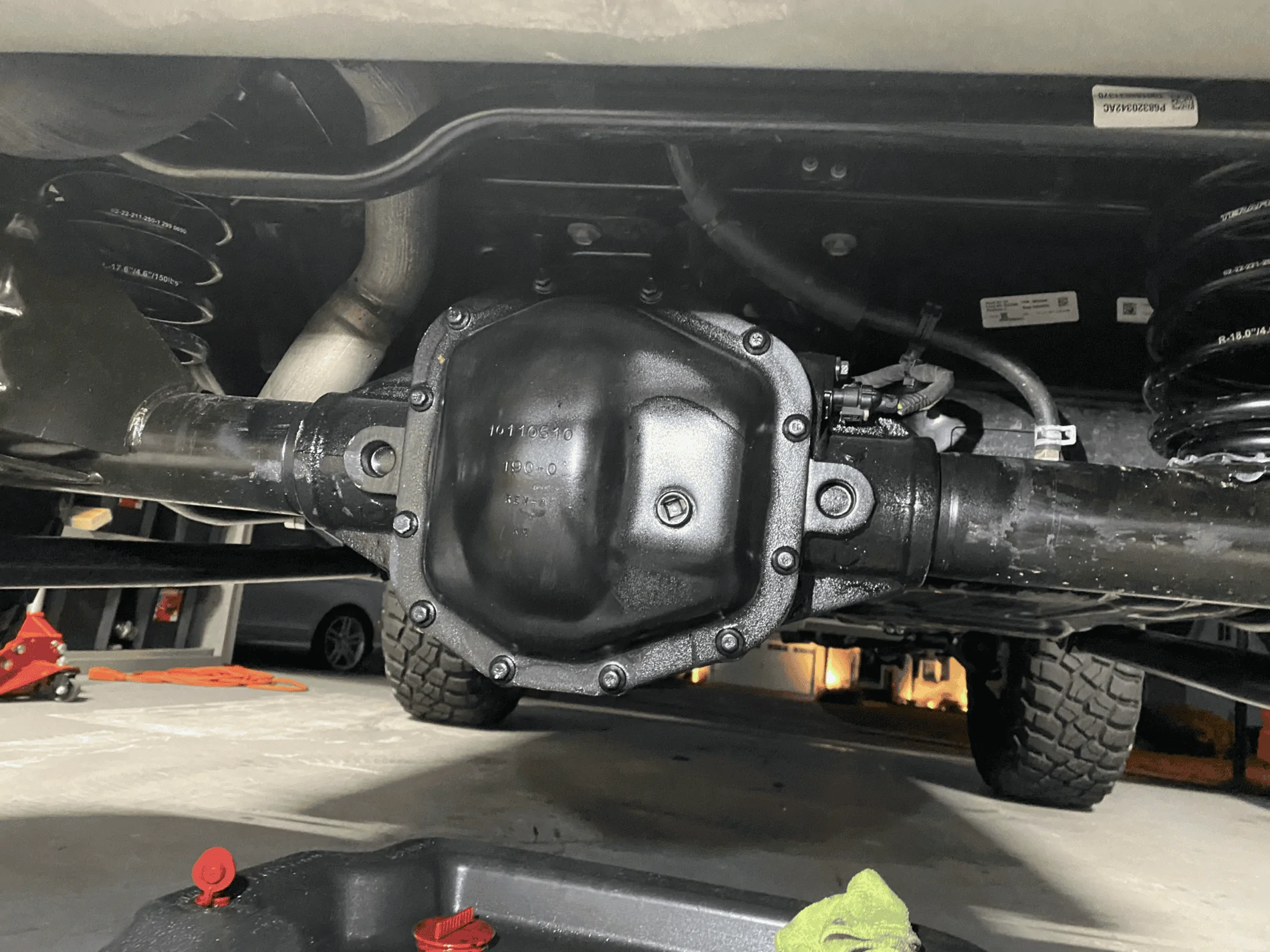
- Using a 3/8" Drive ratchet, drain the diff fluid into your drain pan. Wait for the diff to finish draining. Clean the drain plug and apply teflon tape to the threads. Reinstall at this time.
- Using a 10mm socket, remove the diff cover bolts.
- Using a flathead (or finger tips), remove diff cover.
- Remove the reusable diff gasket.
- Using a 15mm socket, remove the R/H side Cap Bolts.
- Remove Cap Bolts with alignment plate. Keep the bolts with the plate so they go back in the same spots they came out of.
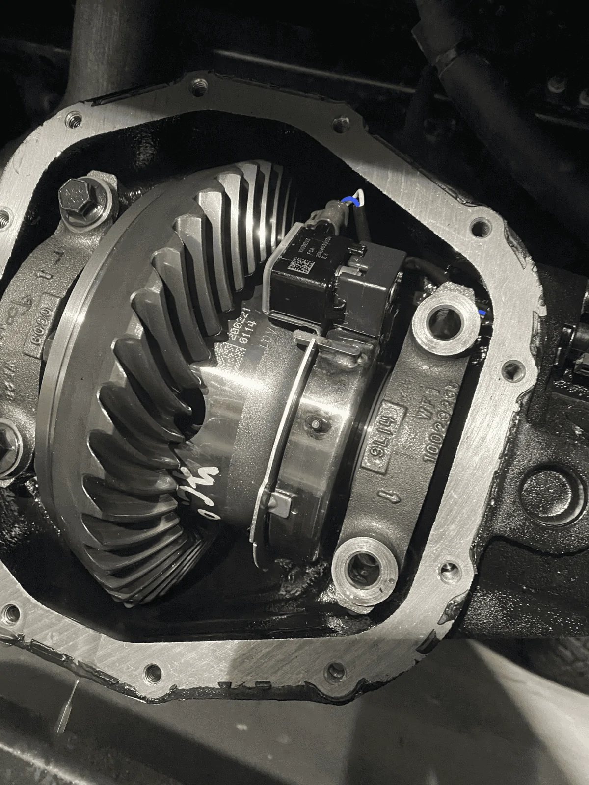
- Using a T20 bit, remove the screw holding the Locker Sensor in place.
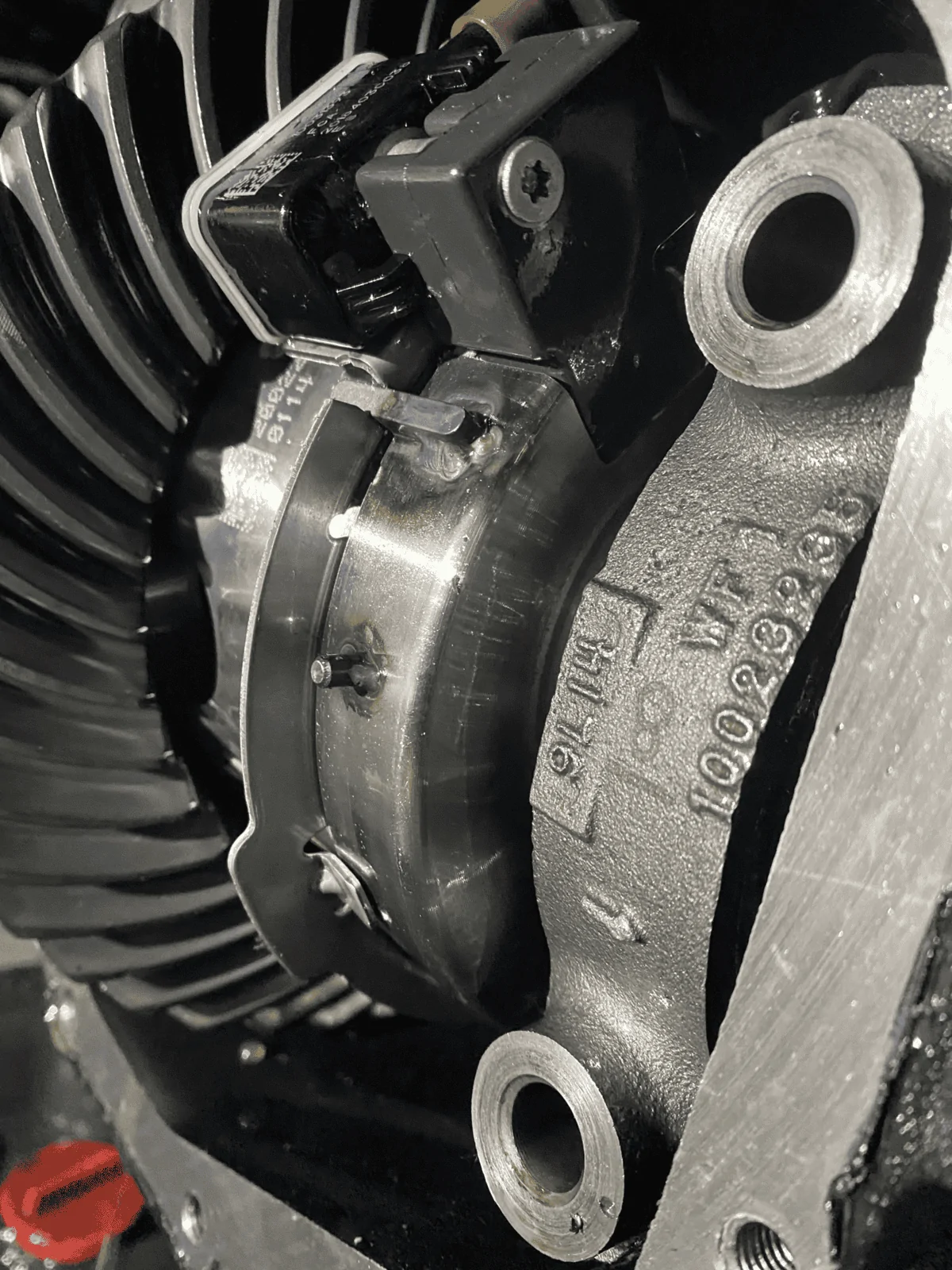
- Using a flathead (or fingers), disengage connector safety clip.
- Remove Connector and Sensor.
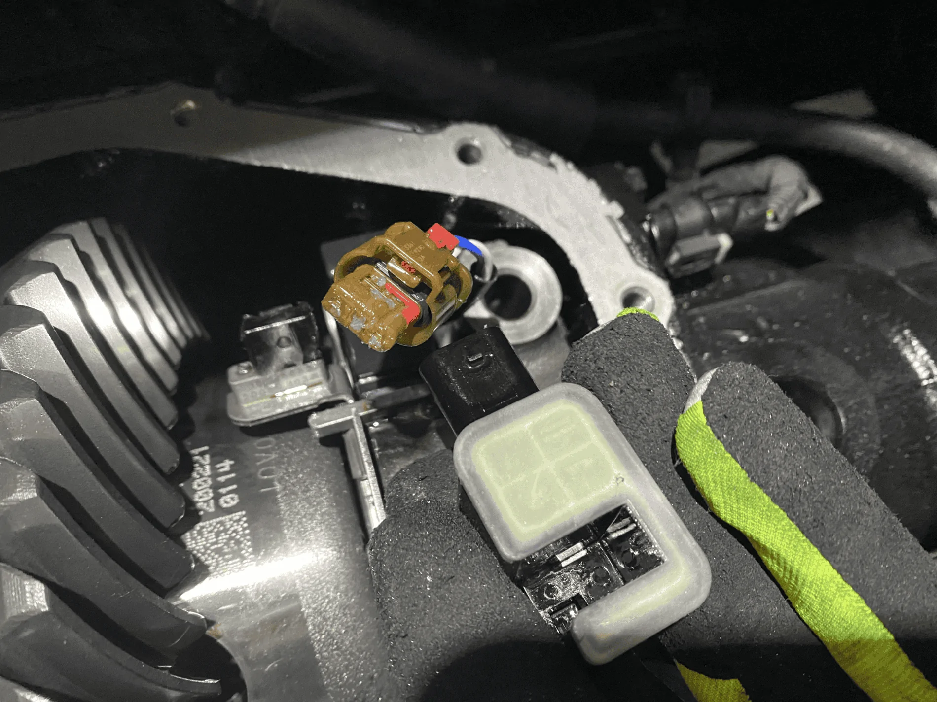
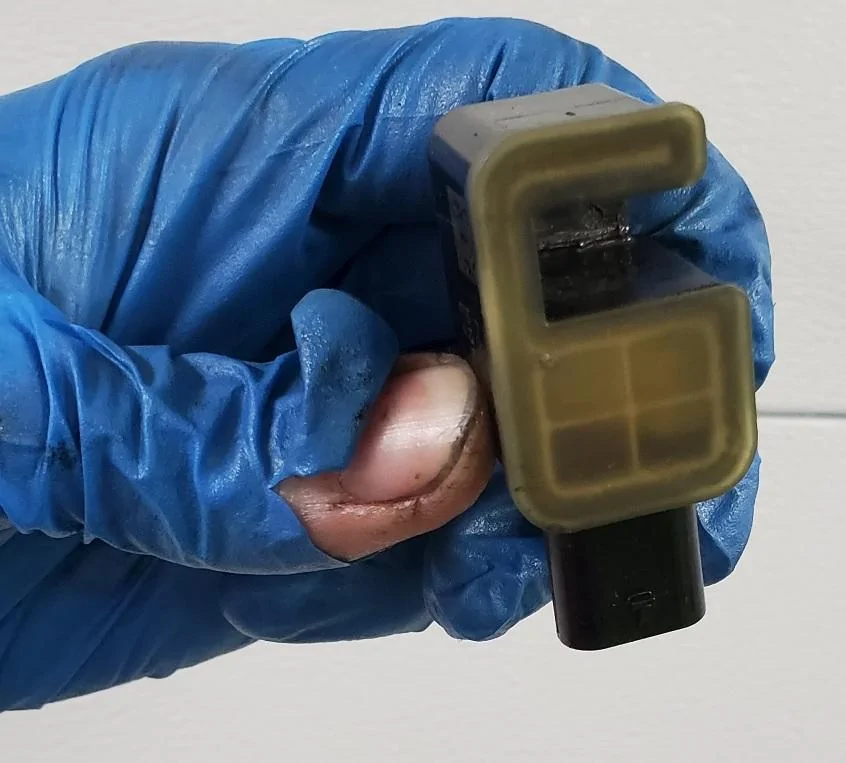
- Wipe sensor off using a shop towel or microfiber cloth.
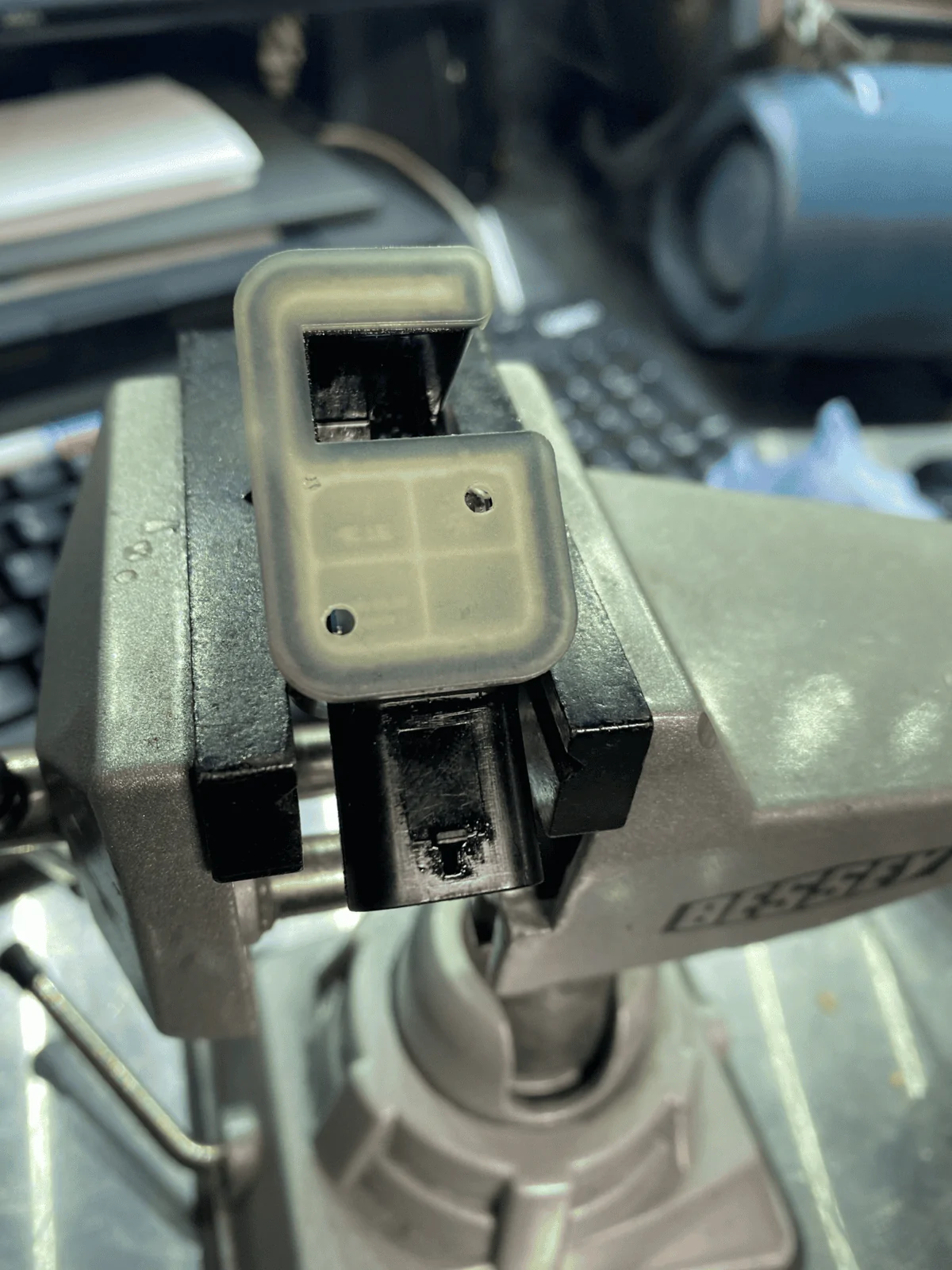
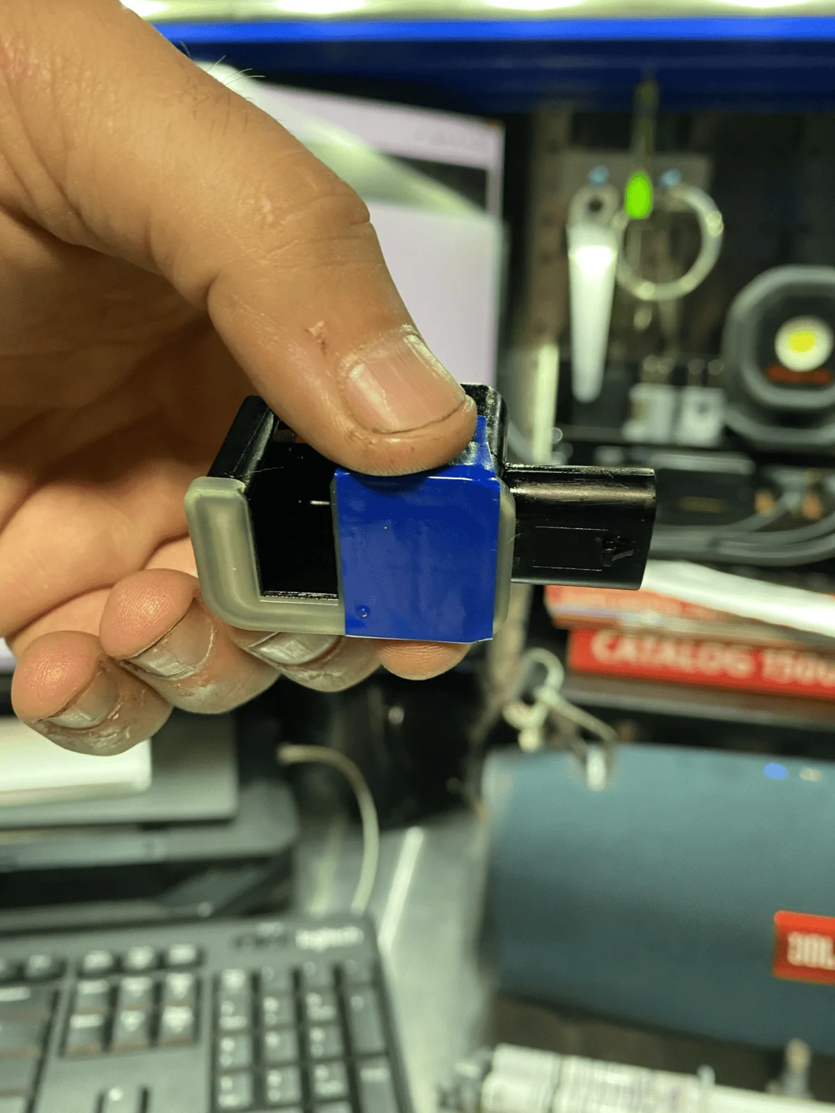
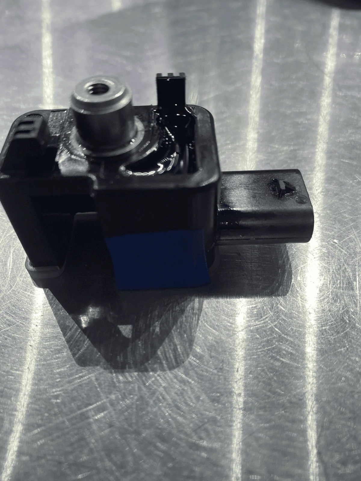
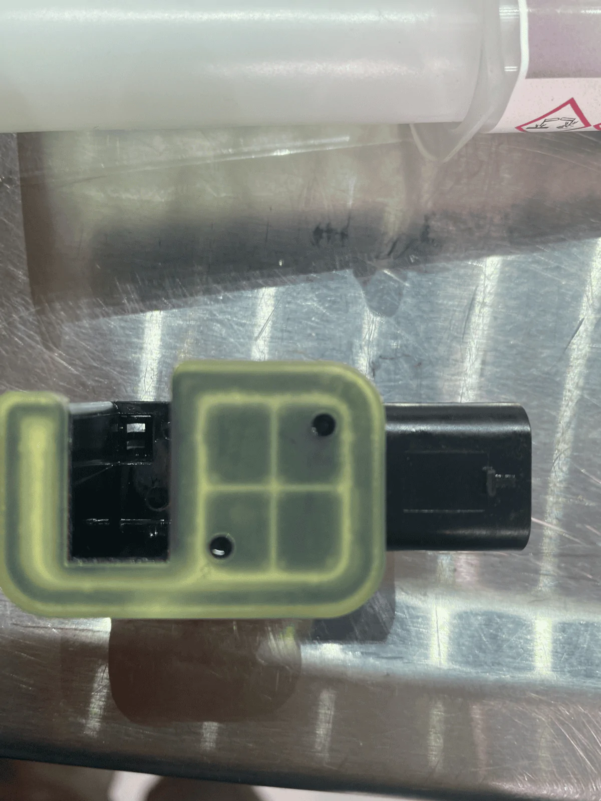
- Mark sensor as shown in the picture with a sharpe.
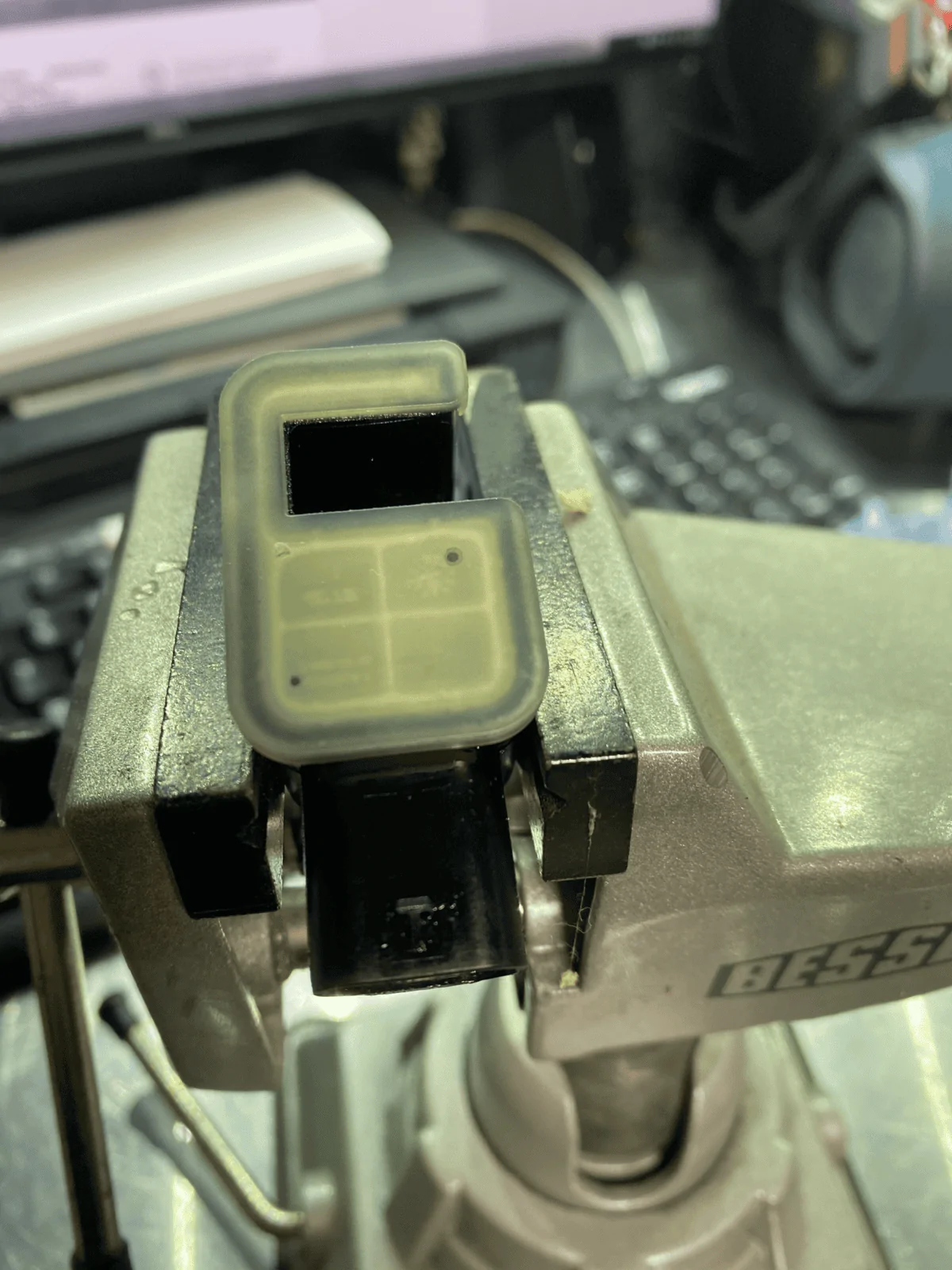
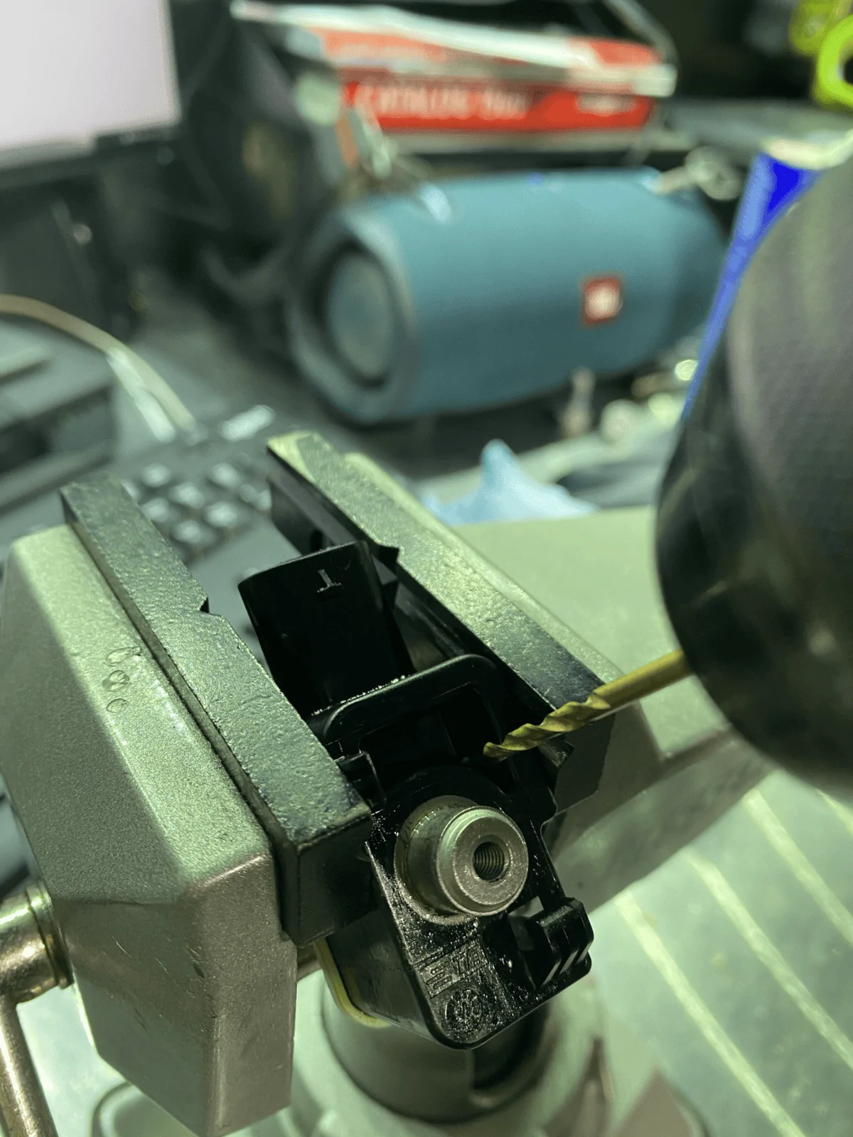
- Using a 3/32" drill bit, drill 3 holes as shown in the pictures. Be VERY careful with this step as the PCB (Circuit Board) is located very close to the clear cap on the sensor. Drill at a very low speed, with light pressure. We need 3 holes for this work properly. One is used to inject potting compound into the top side of the PCB, one for the bottom side of the PCB, and one to let air escape as we are injecting potting compound. Without an air escape, there will be air pockets and this whole thing will be for nothing.
- At this point, if your sensor has oil in it, would be a good time to clean it out. Spray some connector/electronics cleaner through each hole to rinse the sensor out. Be sure to let it dry completely before continuing to the next step. You don't want to dilute the potting compound too much. A little bit is ok.
- Inject potting compound as shown in the video. Once you inject the compound in the bottom hole, you will notice the air being pushed out first and then a rush of compound will come out when it's full.
- Once the sensor is full, wipe the top side off with a shop towel.
- Apply electrical tape over the two holes and set the sensor down on its top.
- Wipe off any excess potting compound and fill the void in the back of the sensor with more compound. Let sit for 3-5 hours. Once tacky, clean the sensor using Acetone so there isn't any left over potting material on the outside of the sensor once fully cured.
- Once cleaned, let sit for 24 hours. (At least 12 hours before reinstallation.)
- Once cured, install sensor in reverse order. (Use Dielectric Grease on the connector and Loctite on the T20 screw.)
- Install alignment plate and R/H side Cap Bolts. Be sure to TQ to spec. The TQ specs are different front to rear.
- Install Diff Cover.
- Service Diff.
- Test Locker System.
Sponsored
Last edited: