OP
OP
jmccorm
Well-Known Member
- Thread starter
- #91
I'm hoping! But here's what I'm stumbling with:This appears to be the CAN IHS connector.
https://www.mouser.com/ProductDetail/571-5-2138650-1
Pull up the 5-2138650-1 datasheet. Look on the far-left side of the PDF document. Do you see the KEYING section? I'll repost what I created earlier since it appears to apply here, too:
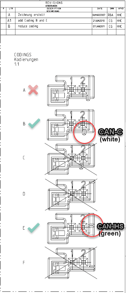
So here's my question:
When you order 5-2138650-1, what kind of key coding are you going to get? I'm assuming "A" (as shown in the picture above) or is there some other way to know for sure, or to select which one you're going to get? Or does it have some way of selecting it yourself? The only key coding that's useful is going to be B and E.
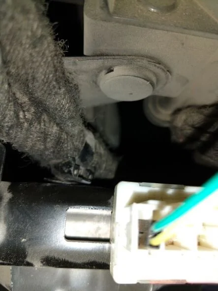
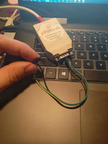
I'll give it a shot! (I also saw it under "Customers Also Bought".)...and I'm hoping that these are the terminals.
https://www.mouser.com/ProductDetail/571-5-963715-6
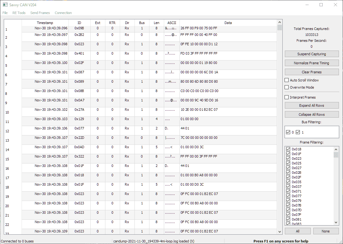
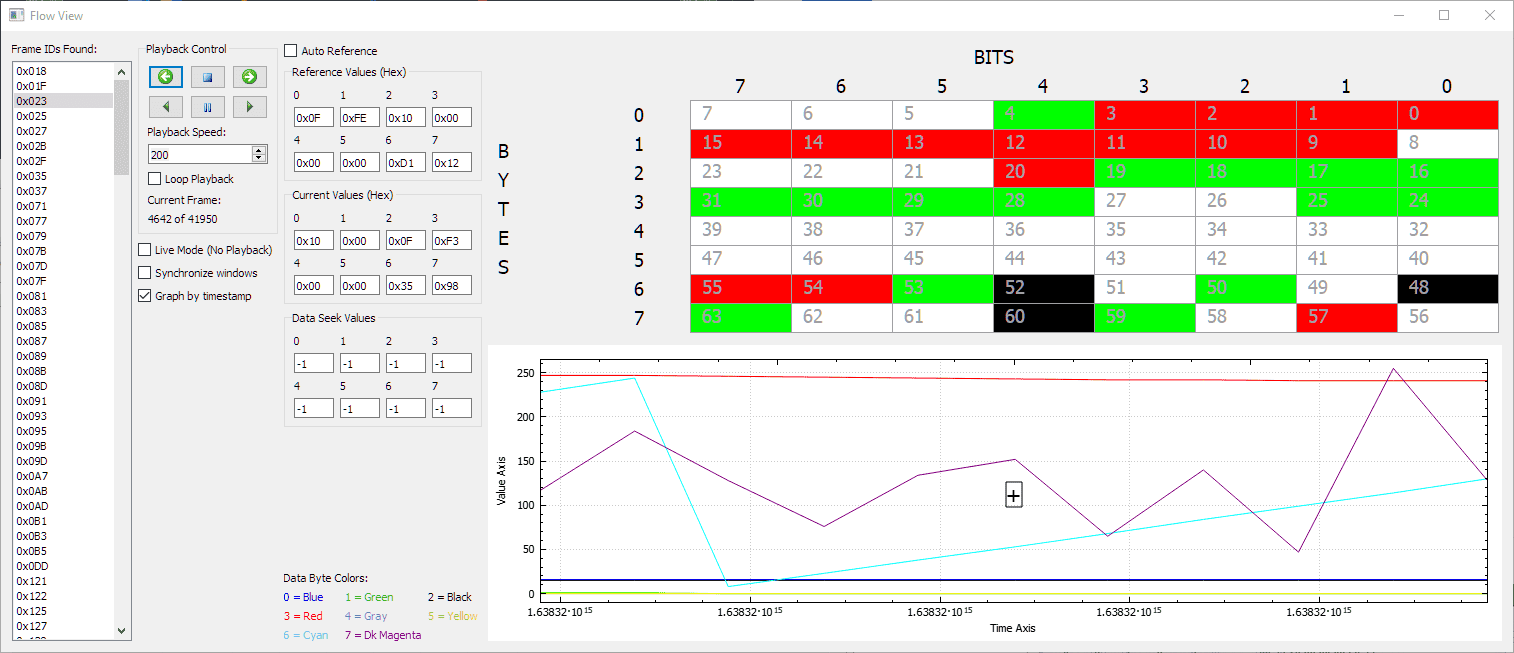
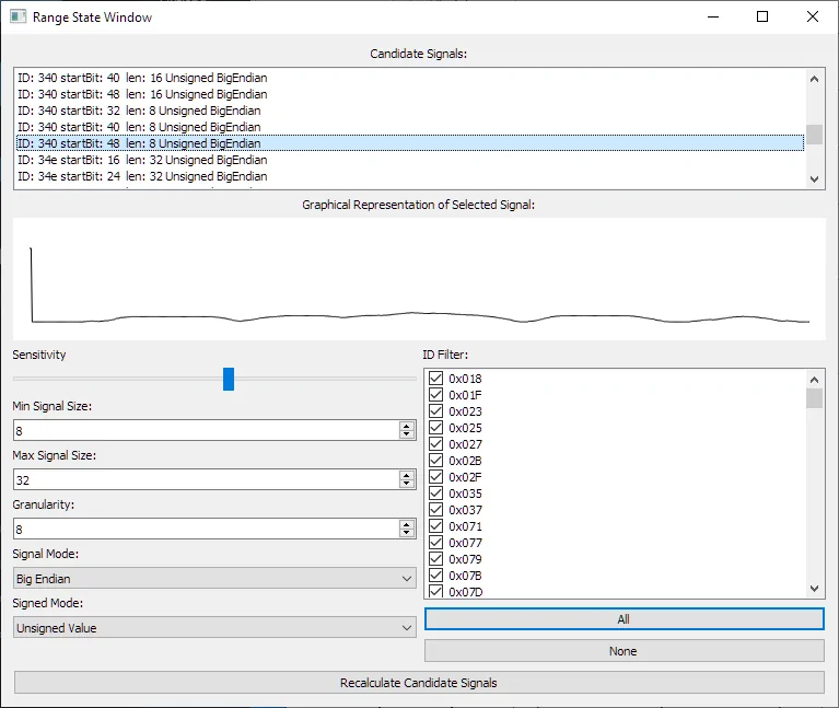
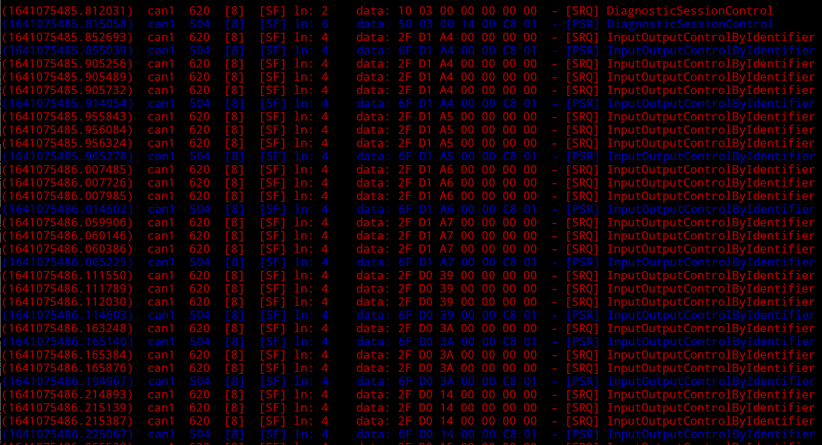
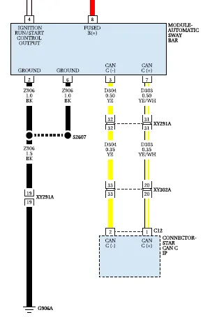
I'll raise that one's priority on my to-do list. I see that the Automatic Sway Bar Module itself lives on the CAN-C bus...I did a little tinkering today trying to find the address used for sending the state of the sway bar switch. I didn't have any luck but this is also my first time messing with the CAN bus. I would absolutely love it if someone can help me track down the codes sent by the sway bar module. My Mojave doesn't have this module so I don't have access to them.
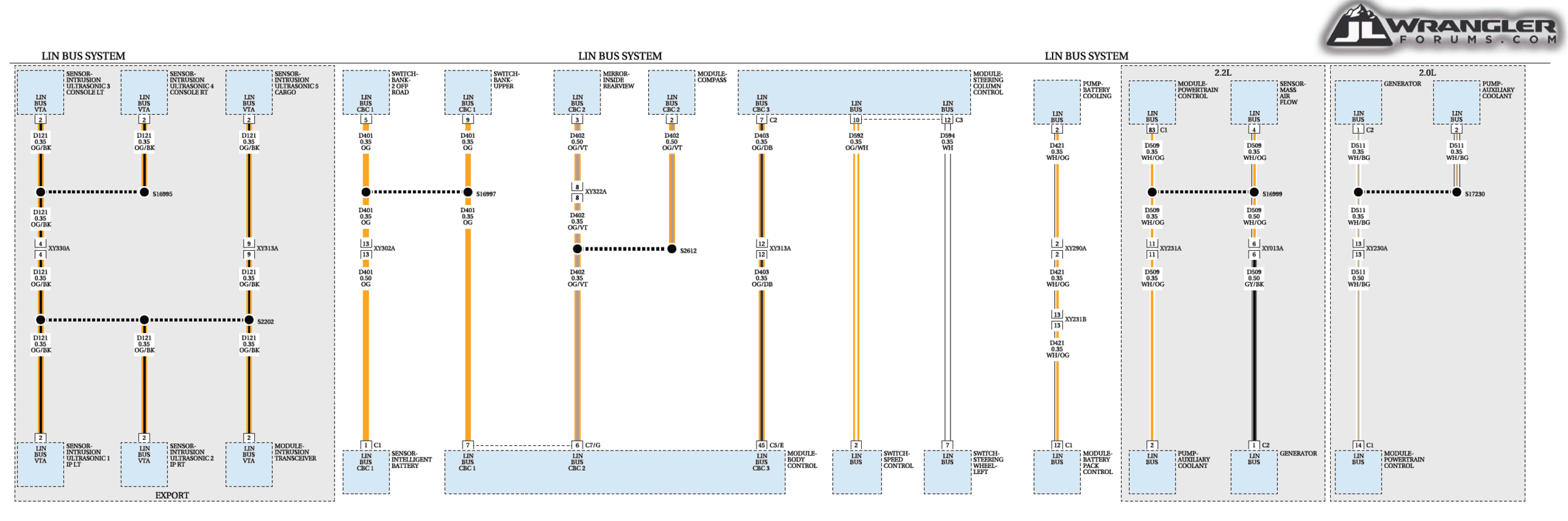
I could not find anything in the Wrangler's wiring diagram which covered just the sway bar switch itself, but I'm hoping it's part of the Integrated Center Stack Switch Bank Module on the CAN-IHS bus:
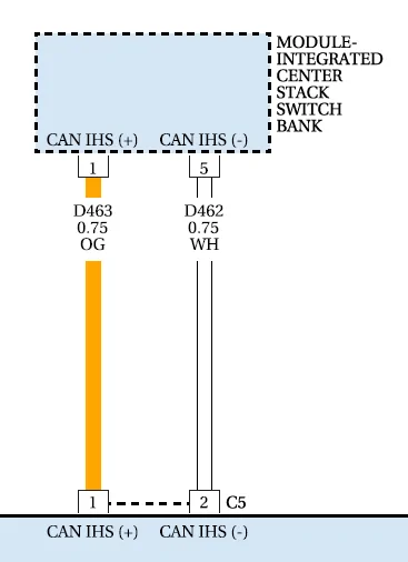
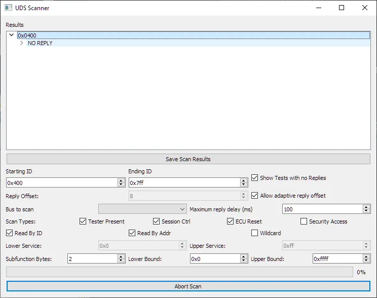
...if so, I've got a tool that'll help identify it pretty quickly.
Sponsored