Sting_NC_USA
Well-Known Member
- First Name
- Michael
- Joined
- Mar 25, 2018
- Threads
- 28
- Messages
- 1,041
- Reaction score
- 1,031
- Location
- Birmingham, AL
- Vehicle(s)
- 2018 Jeep Wrangler JL Unlimited Rubicon
- Build Thread
- Link
- Vehicle Showcase
- 1
- Thread starter
- #1
(If you reply to this post - PLEASE do not quote the entire post! It is entirely too long to be repeated over and over. Thx!)
There was little information available (at the time of this original post) regarding audio wiring schematics for the JL. This thread was put together to serve as a single location for us to build upon. I'll update it periodically until this project is finished (FYI, it's now complete!).
Prior Needs:
When removing the stock speakers, the uConnect system has to be "tricked" into sending its audio signal to each speaker. In short, the Jeep's uConnect system checks for the proper resistance load introduced by our stock speakers.
If uConnect doesn't detect the proper resistance on any particular channel, the system turns that channel's signal off. I'd originally found only one option that worked (see the Resistor approach below). If you're interested in reading more about how the resistor approach works, this is a great article on the topic: Everything is hooked up but no sound is playing, just don't buy the Audio Control AC-LGD device it discusses. I'll elaborate...
I tried the AudioControl AC-LGD device, and it worked... sporadically. Evidently the resistance tolerances for the AC-LGD were too narrow causing it to work sometimes, and not others.
The JL Audio FiX-LSA-4 (a device similar to the AudioControl AC-LGD, but made by JL Audio) didn't work at all with the Jeep's load sensing issue. I spoke with a JL Audio tech, and this seems to be a known issue they'll likely address soon. The reason appears to be related to a difference in the Ohm load our stereo systems require vs. others.
This leads us to the two functional options for overriding the load sensing issue.
Option One: VERY EASY (and inexpensive) to do and requires light soldering:


Option Two (Recommended): PAC Audio AP4-CH41R2

Premium Radio:
Premium Amp location (under the steering wheel) and modular plugs:

______________________________________________________
Sub-woofer only install:
______________________________________________________
Here are several additional details you may find helpful if the above hasn't scared you away yet...
On the Base System, there are four 4-inch speakers and four small tweeters. I ended up upgrading the Soundbar and the Kick Panels to 5.25-inch separates (Separate Woofer and Tweeter - also called "Components"). Now that Metra has introduced their new speaker pods, I can no longer recommend anything other than 6.5's in the kick panels, and here's why...
The Kick Panels:
The newly introduced Metra JP-1014 Speaker Pods, announced and released shortly after SEMA 2019, significantly simplify the kick panel speaker upgrade process. I have updated this post to recommend running 6.5-inch separates up front and 4-inch coax's in the soundbar if you don't want to modify the Soundbar much, or 6.5's if you run the SSV Works adapter. Going larger in the soundbar without the SSV Works adapter is possible, though it will require more cutting than I personally recommend, given the limited sound that can be achieved from the soundbar.
NEW: Installation Tip (Pictures added) - You DO NOT need to remove the entire dash to change out the Kick Panel pods!
To access/remove the speakers in the kick panels, you have to remove the two side dash panels (body clips hold the driver/passenger side on - pry off carefully) to access the screws dedicated to securing the dash's sides.

The displayed, partially removed screws below are the only screws that must come out from under these panels, except there is one hidden screw recessed in the side of each Speaker Pod. The recessed screw is accessible within one of those larger silver "holes," and you can access it with a short Phillips head screwdriver. Once again, this applies to both the passenger and driver's side panels.
Then, you'll need to remove the plastic panel under the steering column (body clips - pull the panel directly towards the driver's seat).

On the passenger side, remove the glove box (depress the latch at the top-inside of the glove box to pull it down and outward). Then, remove the three black dash screws under the area where the glove box was. Only the black 7mm screws need to be removed.

On the driver's side, each of the black 7mm screws visible here must be removed.
(Edit: Provided by @onspeed) Another Little tip regarding the driver side speaker pod removal. The metal bar that sits under the pod that causes all the grief is held in by 4, easily accessible bolts; two 10mm and two 8mm. Remove the left most 3 and the bar is able to flex easily out of the way to drop the speaker pod down.
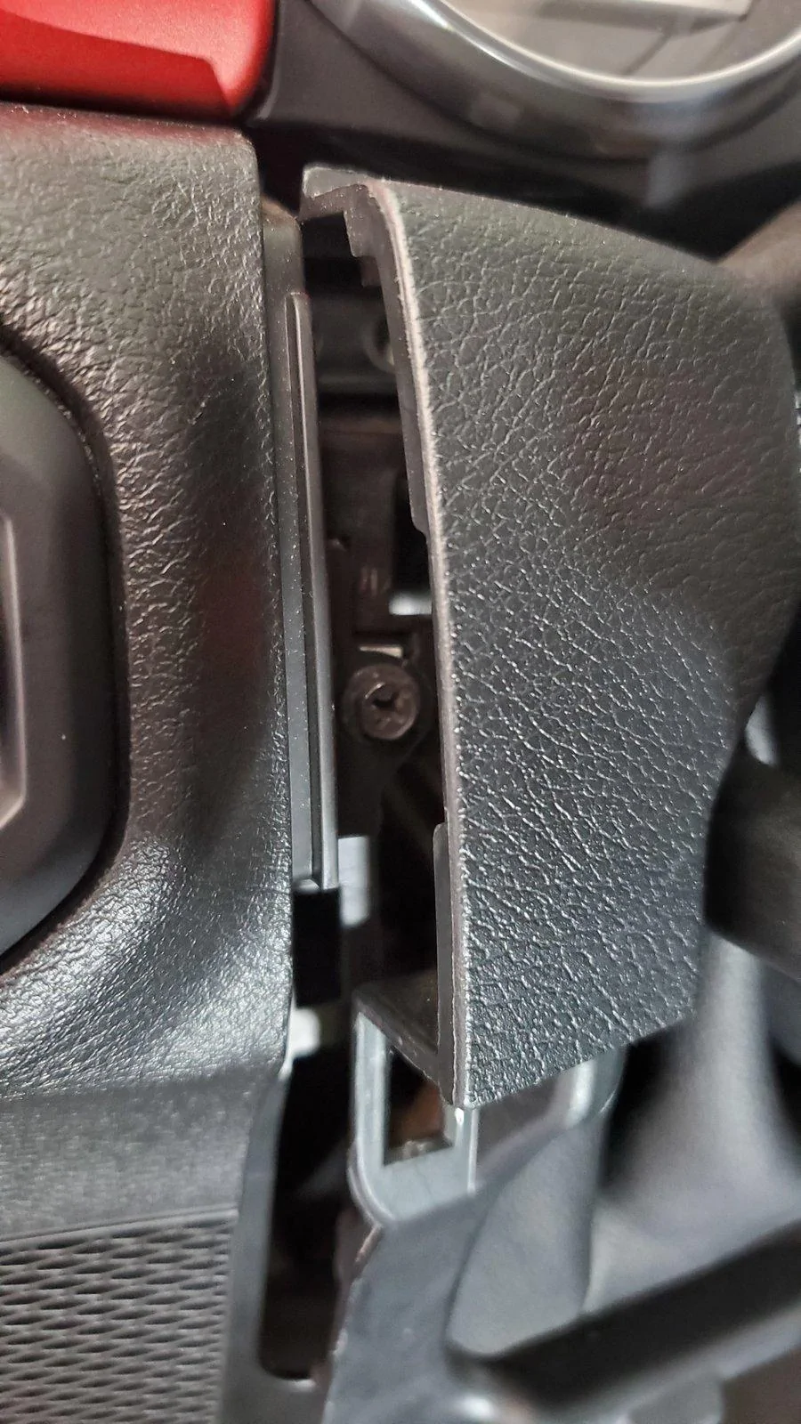
Oh, and don't forget to remove this screw, too. It's tucked in just to the right of the Headlight/Dimmer pod, and removing it will give you much more space when rotating the driver's side Pod out.
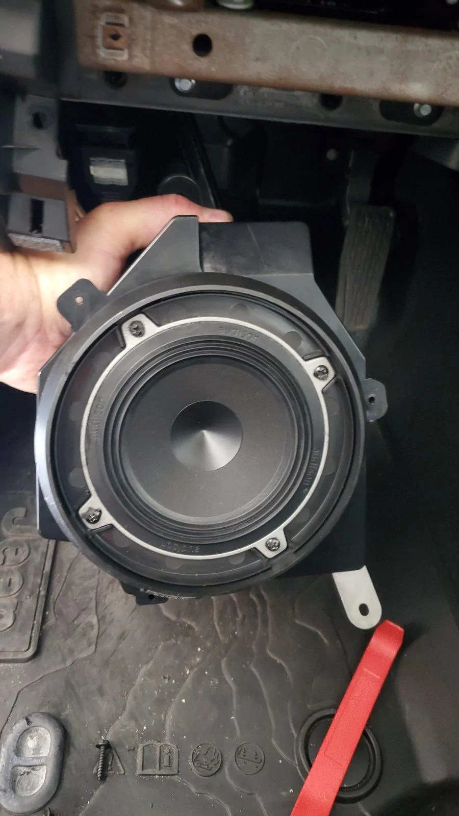
As mentioned, each of the Kick Panel speakers have a hidden screw recessed in the side dash panel area, as well as a screw at the top and bottom of the enclosure itself. Once all 3 of each speaker enclosure's screws are removed, you may carefully pull the bottom section of the dash away from it's mounts to access the Pods. Doing so allows you to rotate the speaker enclosures out. Be careful that you don't pull the dash so far out that you crease/pinch the dash covers.
The passenger side Kick Panel Speaker Pod rotates out easily, so there's no additional feedback provided for it. Simply unplug the speaker wire plug on the back, and you're done here!
There are a few NEW tricks to getting the driver's side Pod out easily.
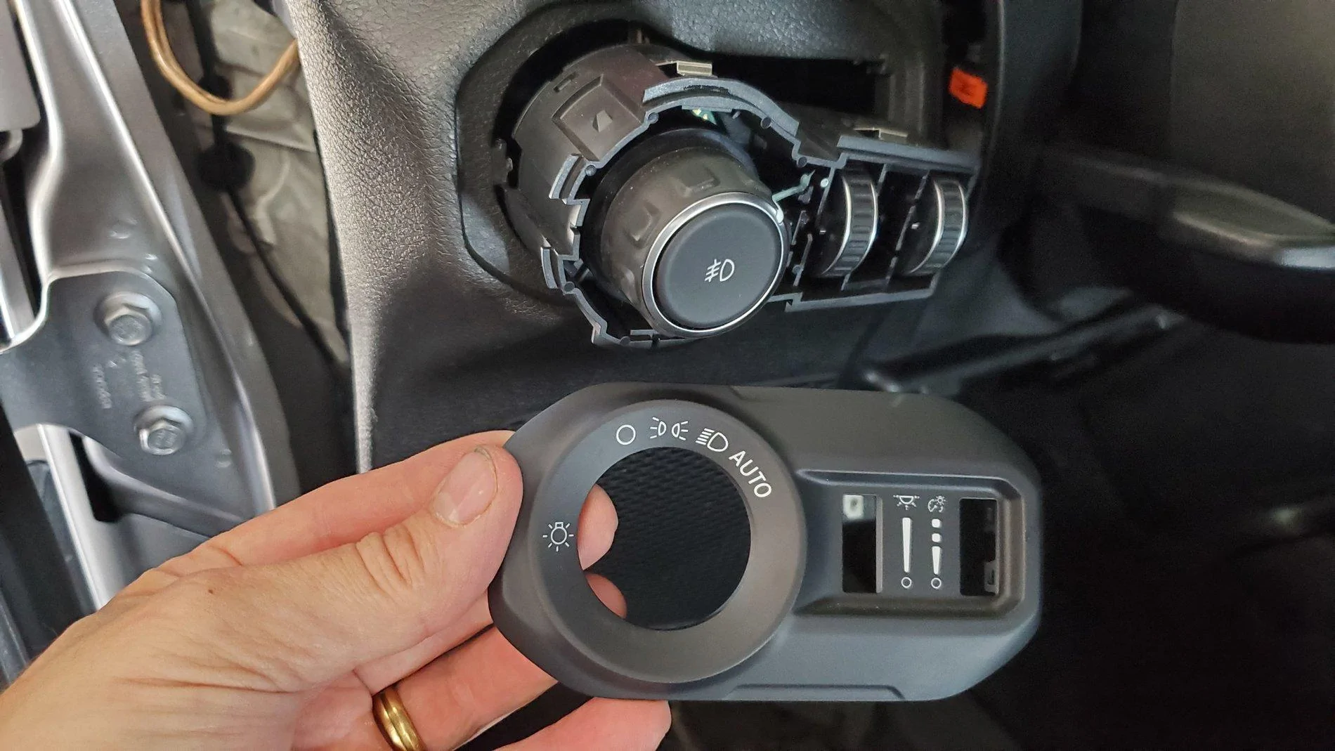
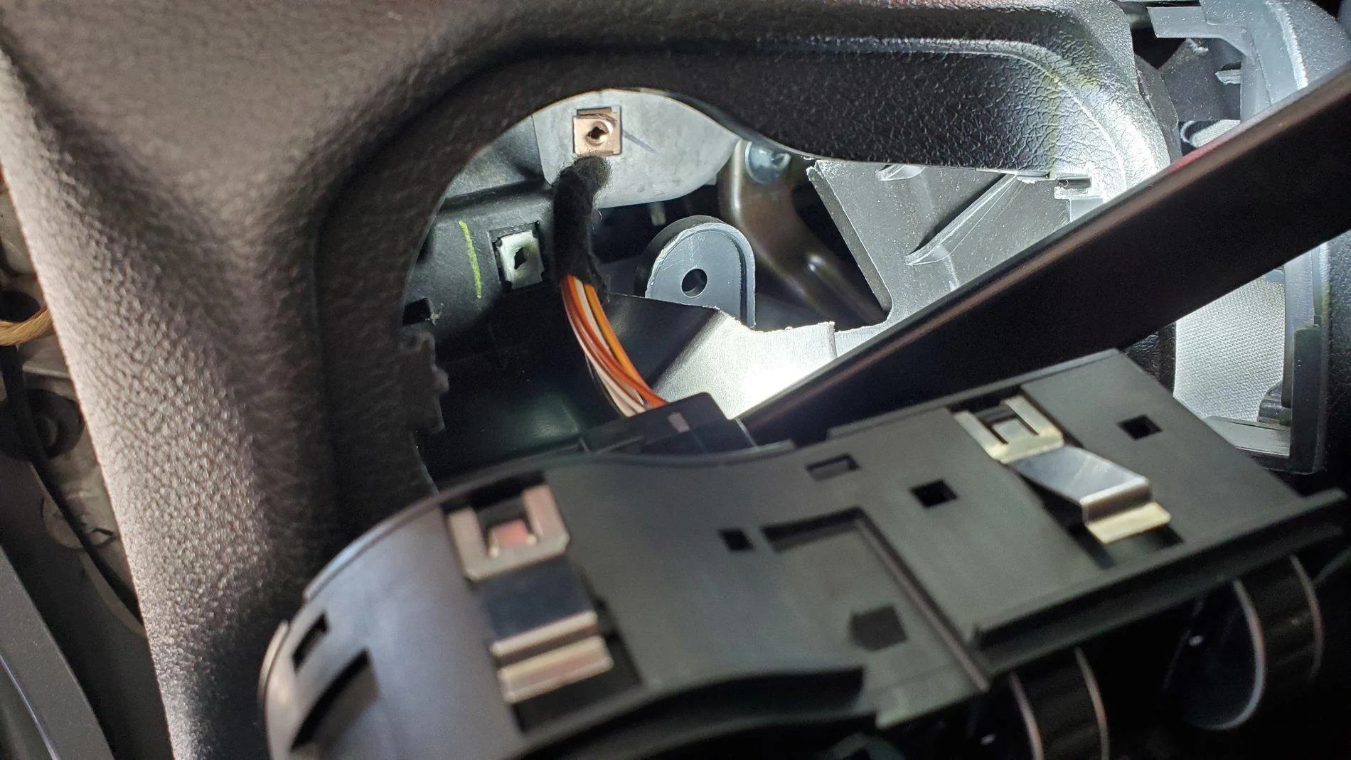
After removing the side dash panel, the panel under the steering wheel and all of the screws previously shown, pop off the cover for the Headlight knob and Dimmer wheels using a pry tool.
Next, from behind the dash, use your fingers to compress the silver tabs on the Headlight Knob/Dimmer plug. This will allow the assembly to easily pop out and provide access to the top Kick Panel Speaker Pod's mounting screw. Two clips on the top, and two clips on the bottom of the Headlight/Dimmer plug allow it to easily be pulled out, and there's no need to disconnect the wires.
Here's the screw location for the top of the Driver's side Pod. Using a magnetic screwdriver will help in removing and re-installing this screw, as it's recessed a bit behind the Headlight/Dimmer pod. You can also use tape to temporarily hold the screw onto the screwdriver when re-installing.
The above photo is from a non-premium system. If you have the premium system, the GPS antenna partially blocks the upper pod speaker screw and taking up space.

Once the side, top and bottom pod screws are removed, there's another trick to share regarding the removal of the driver's side Pod.
To do so, pull the dash section's you've loosened outward with your right hand, being careful not to crease any parts of the dash by bending it. Run your left hand up the inside of the dash to guide the top of the Pod. Then, with your right hand on the bottom of the Pod, lift up on the Pod, pushing it up into the dash as far as it will go, then, using your right hand, pull the bottom of the Pod towards you. It will pop over the metal dash frame that's under it, and you'll be able to rotate it out after that. You may need to rock the bottom of the Pod back and forth a few times while lifting up on it.
There's a black box connected to the back of the driver's side speaker with three screws. It's called a Gateway, and it's actually one of the things that makes the driver's side Pod so difficult to remove. You'll need to unplug both of its modular plugs (unless you're already running a Tazer JL) before removing the driver's side Pod.
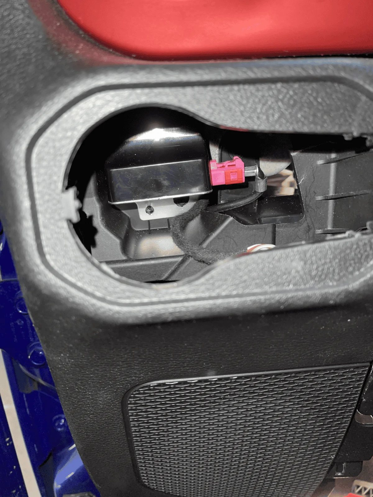
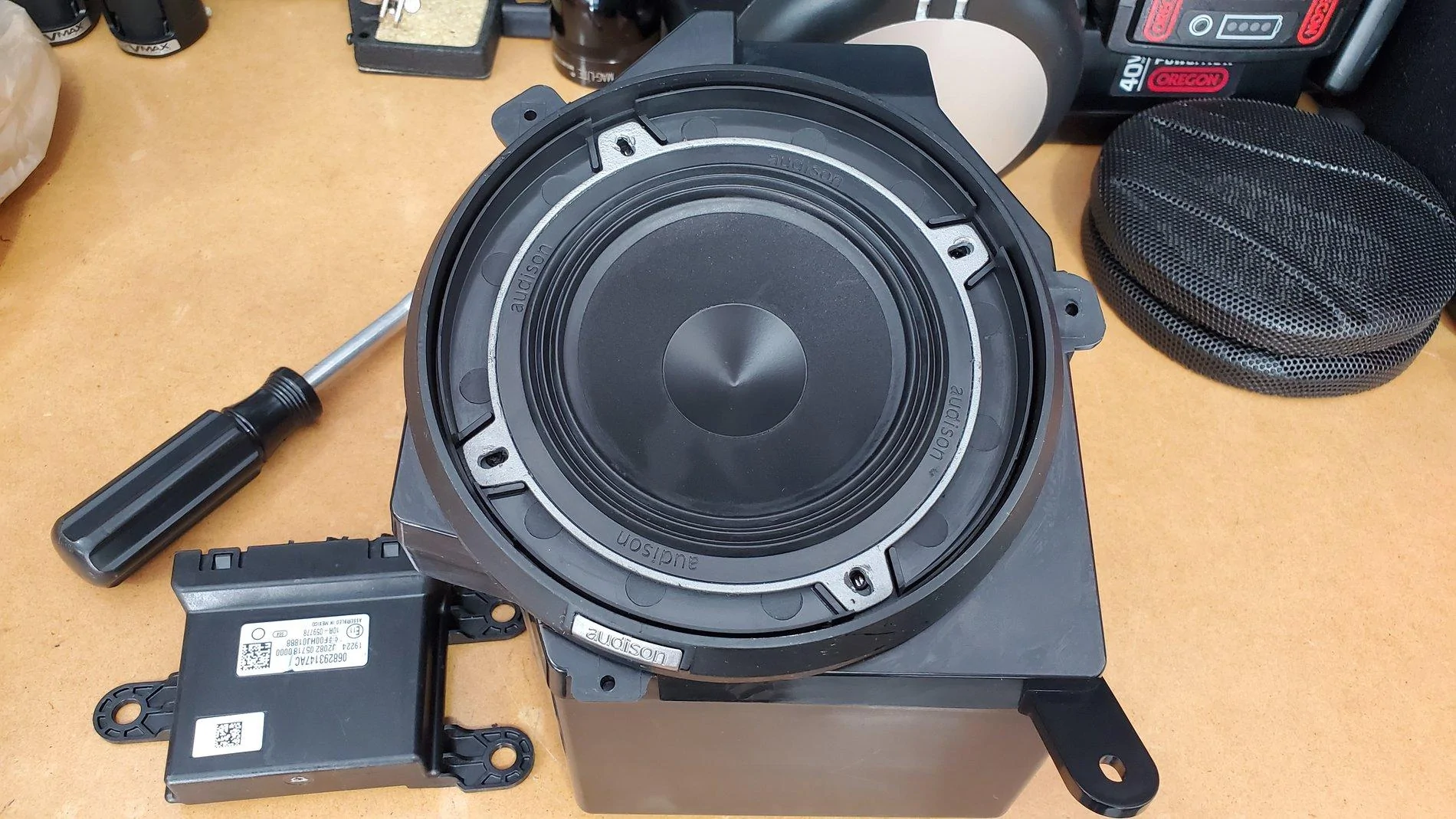
Important: If you re-install your Metra Pods and your stereo doesn't turn on, it's likely because you didn't plug the Gateway's modular plugs back in. (This is the most requested question I receive!) The Gateway is the device in the bottom left of the following picture, and the driver's side Metra Pod has a place for this to be mounted on the back.
There's also a rather large hole on the back of the Metra Pod. The stock Mopar pods you removed have rubber plugs that you'll want to transfer. Just be sure to run your speaker wires through these rubber plugs before adding wire connectors and before trying to re-install the Pods.
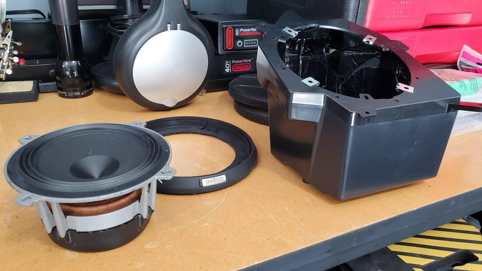
Pictured below is one of the new Metra pods before the speaker's installed and another picture before the finished Pod is ready to be installed.
Note that I'm running 5.25-inch separates, yet these Pods are made for 6.5's. By using the speaker manufacturer's (Audison in this case) provided housing, the housing sits right over the 6.5-inch holes. Also, on the passenger side pod, there will still be a few screw holes open. Make sure you seal each unused hole with silicone, and/or a small screw, or it could end up "whistling."
While not shown, I did add sound deadening material inside the box, polyfil inside the box and also cut a gasket from the sound deadening material that sits between the speaker ring and the Metra Pod. The gasket simply seals out any air from the remaining, unused screw holes under the speaker.
To re-install everything, simply reverse the order above, ensuring all screws, clips and plugs go back nice and easy. There's no need to force anything.
When re-installing the driver's side Pod, you'll benefit by viewing the top bracket through the Headlight/Dimmer portal, ensuring it's at the location shown below before pushing the Pod up as far as it will go. Once you verify it's in the right spot, begin wedging the bottom of the Pod inward towards the front of the car. If you don't have the top section in the right spot, you'll struggle with pushing the Pod upward enough for the bottom and Gateway to clear the metal frame bracket. It really shouldn't require much force.
The Soundbar:
If you do choose to upgrade to larger speakers in the soundbar, modifying the soundbar to accommodate larger speakers is fairly straight-forward. It takes some time/skill with a Dremel tool to enlarge the speaker cavities. You can fit a decent pair of mid-range coaxial speakers up there, or you could choose speaker separates. Each of the rear channels in the sound bar has a mid-range speaker and a separate tweeter already, so separates are possible, you'd just have to wire them on your own. Meaning, the stock mid-range woofer and tweeter on each channel share the same two wires (they aren't discreet). For separates, you would use the wire going into the mid-range woofer to connect to the separates' crossover, then run a new wire from the crossover to the new woofer and new tweeter.
Note, I rate upgrading the Soundbar speakers as "beginner" level install if you stay with 4-inch speakers, and as an "intermediate" level install if you up-size your speakers to 5.25-inch or larger.
I have deleted all "concerning" commentary previously shared regarding upgrading the kick panels now that the Metra pods are available. With the Metra pods, we are now presented with such a great option that I can't recommend anything other than using them with 6.5-inch separates. Advice: Invest the majority of your sound system money in the front soundstage, and use the soundbar speakers as nothing else but "fill" speakers.
If, after that advice, you still choose the Resistor route and use the JL Audio Fix™ 86, there is a calibration process necessary that requires a little patience. When calibrating the device, you must be 100% successful in "tricking" all four channels of the uConnect system into turning themselves on. If calibration doesn't work, meaning all channels didn't come on and all 4 lights on the JL Audio Fix™ 86 aren't green during the calibration, you should check your wire connections and possibly your solder points for the resistors. I had one resistor that didn't work initially - it happens.
VERY IMPORTANT: Ensure you are using the JL Fix86's test track for the calibration. JL Audio offers the file as a download. You can't simply copy the file off of the CD. It needs to remain a high-quality source, and you should ensure that sound will play on your system before attempting the calibration process.
Note that, if the JL Audio Fix™ 86 calibration process fails, you have to power down the receiver (key off, and away from the vehicle for about five minutes) until the radio fully resets. You'll know you're successful with the reset if the radio displays the disclaimer screen and boots up as normal. This is due to the fact that once the uConnect system detects a stock speaker isn't there, and the resistor override isn't functioning (for whatever reason), it has to be completely powered down and allowed to reset before uConnect will initiate a new load sensing test. On the plus side, once everything is connected and calibrated, you'll have the cleanest and flattest signal possible from a stock radio. And, you can plug your laptop or phone into the JL Audio FiX™ 86 to tweak the settings and EQ!
As with anything aftermarket, please understand you are taking any install advice provided here into your own hands, and at your own risk. I have to recommend that any power wiring, especially when wiring directly to the battery, be fused at the battery/source. In the case of a short, this blows the fuse instead of creating a new welding source! I also recommend using basic relays for your remote connections, which reduces the risk of feeding power back into your Jeep's electrical system due to a faulty amplifier or component.
Thanks,
Mike
PS: For any jlwranglerforums.com members wanting to venture into upgrading their sound systems, I've arranged a contact that can assist you with purchasing the proper equipment. He'll be happy to advise on gear that fits your needs and budget, and he's agreed to offer discounts to our members if you mention you saw his name here. To get started, contact Travis Grim @ 704-530-2073. He's based near me in the Charlotte, NC area, is a fellow Jeep owner and has approved the sharing of his contact information. All I ask: If you use him as a resource and plan to buy, please buy from him. He's a highly knowledgeable, low pressure manager engaged with a large Charlotte audio/video outfit.
PPS: Don't skimp on your main power wire. There are several types of wire available with the two primary versions being CCA and OFC. Get OFC. It transfers power more efficiently and runs cooler.
______________________________________________________
Base System Speaker Wiring

There was little information available (at the time of this original post) regarding audio wiring schematics for the JL. This thread was put together to serve as a single location for us to build upon. I'll update it periodically until this project is finished (FYI, it's now complete!).
Prior Needs:
- Wiring Schematic, including specific wire colors
- Base System (Solved - See below) - The Speaker Wiring Schematic is now provided to help identify positive/negative polarity
- Alpine System (Solved - See below)
- Override UConnect load sensing test (UConnect checks for the stock speaker resistance and turns individual outputs off if not "seen." (Solved - See below)
When removing the stock speakers, the uConnect system has to be "tricked" into sending its audio signal to each speaker. In short, the Jeep's uConnect system checks for the proper resistance load introduced by our stock speakers.
If uConnect doesn't detect the proper resistance on any particular channel, the system turns that channel's signal off. I'd originally found only one option that worked (see the Resistor approach below). If you're interested in reading more about how the resistor approach works, this is a great article on the topic: Everything is hooked up but no sound is playing, just don't buy the Audio Control AC-LGD device it discusses. I'll elaborate...
I tried the AudioControl AC-LGD device, and it worked... sporadically. Evidently the resistance tolerances for the AC-LGD were too narrow causing it to work sometimes, and not others.
The JL Audio FiX-LSA-4 (a device similar to the AudioControl AC-LGD, but made by JL Audio) didn't work at all with the Jeep's load sensing issue. I spoke with a JL Audio tech, and this seems to be a known issue they'll likely address soon. The reason appears to be related to a difference in the Ohm load our stereo systems require vs. others.
This leads us to the two functional options for overriding the load sensing issue.
Option One: VERY EASY (and inexpensive) to do and requires light soldering:
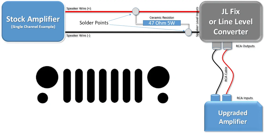
Talking with the techs at PAC, and confirming via online references, a 47 OHM, 5 Watt Ceramic Resistor can be soldered to each pair of speaker level input wires feeding a Digital Sound Processor (DSP) such as the JL Audio FiX™ 86 or equivalent. DSP's help to flatten/condition the pre-EQ'd signal sent by the uConnect system.
I tried this process, and it does work. You can order resistors here, and you'll find that they are very inexpensive. If you go this route, I recommend buying several more than you need, just in case you break a few.
Each resistor is soldered to the (+) and (-) stock speaker wiring pair that you'll use to feed each line level converter input. If you're running a 4 channel amp, you'll need to purchase 4 resistors.
Once again, this tricks the uConnect system into thinking the stock speakers are still there, allowing the system to turn each channel on without having the stock speaker attached. A home-made schematic of this resistor setup is included below.
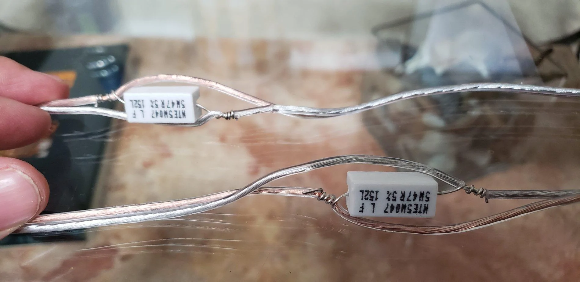
And here's a photo of the resistors installed on the speaker wire, right before they enter the JL Fix86. Note that these weren't yet soldered and wrapped.
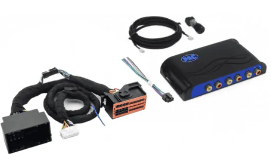
Option Two (Recommended): PAC Audio AP4-CH41R2
I was hesitant to update the post with this device initially, as I hadn't installed one personally. PAC has now updated their website to indicate the second revision (R2 in the model number) supports the Jeep JL and JT! The catch is it's a bit pricey! MSRP is originally at $349, though it can be found cheaper online. If you go this route, just make sure it's the R2 edition!
Since the original posting, I have had the opportunity to install and calibrate the PAC device, and it does a good job of flattening the uConnect's signal. While I still recommend using a DSP like the JL Audio FiX™ 86 or equivalent, you can now effectively use the PAC Amp Pro as the sole "LOC" to feed a clean, low-level signal to your amp(s) via RCA Cables.
Base Radio:
Option 1 - Resistor Approach: For the speaker level inputs of the line output converter, I tapped into the speaker level outputs directly behind the Base System's radio. Those wires were extended and run through the middle console to the back of the Jeep, to my JL Audio FiX™ 86 where my amps are. Once again, wiring colors are available below.
Option 2 - PAC Amp Pro approach: Plug the PAC Amp Pro's harness into the back of your stock radio, plug the radio's harness into the PAC Amp Pro, Connect a 12v Remote wire to your front 12V Adapter's positive wire, set your DIP Switches per the manual and then calibrate it. RCA Cables run from the PAC Amp Pro to your amp, or to your DSP and then your amp.
Premium Radio:
Option 1 - Resistor Approach: For the speaker level inputs of the line output converter, you'll need to tap into the speaker level signals that are coming out of the stock amp, located under the steering column.
Option 2 - PAC Amp Pro Approach: Same Option 2 for the base radio above, but check the PAC Amp Pro's DIP Switches and set via the supplied instructions.
Premium Amp location (under the steering wheel) and modular plugs:
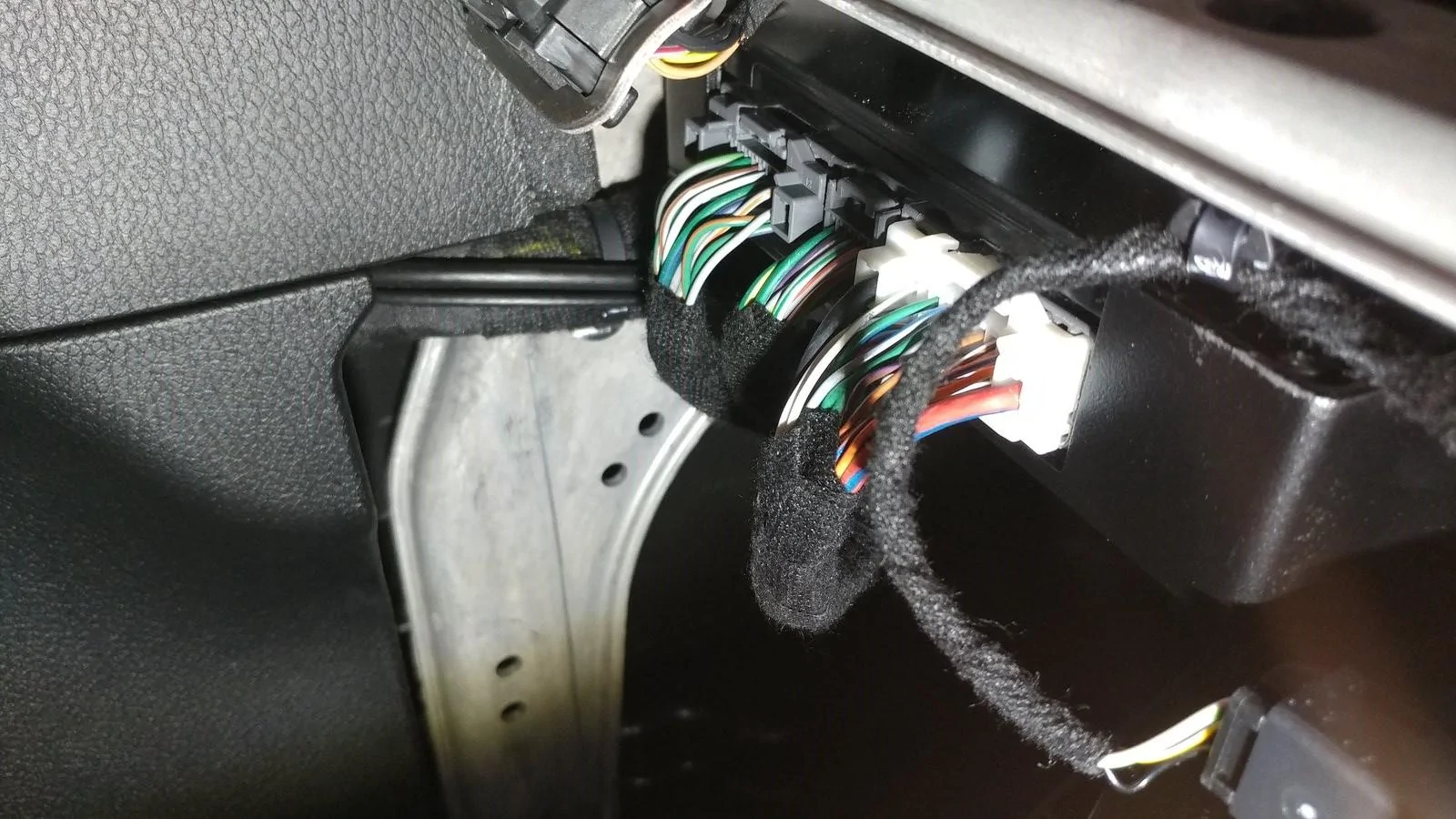
______________________________________________________
Sub-woofer only install:
If you are simply adding a sub-woofer and plan to keep the stock speakers intact, you can skip the resistor or PAC Amp Pro processes described above. Instead, you'll simply tap your connections into the rear speaker wires housed in the B-pillar, behind the passenger seat at the floor level. The wires are easy to find after removing the plastic cover at the base of the pillar. The soundbar speaker wires are the only twisted pair wires down there, and they match the colors in the chart provided. Note, unless your amp has a line output converter built in (doubtful), you will need to add a line output converter (LOC). The AudioControl LC2i, or comparable device, works fine for a sub-only upgrade.
______________________________________________________
Here are several additional details you may find helpful if the above hasn't scared you away yet...
On the Base System, there are four 4-inch speakers and four small tweeters. I ended up upgrading the Soundbar and the Kick Panels to 5.25-inch separates (Separate Woofer and Tweeter - also called "Components"). Now that Metra has introduced their new speaker pods, I can no longer recommend anything other than 6.5's in the kick panels, and here's why...
The Kick Panels:
The newly introduced Metra JP-1014 Speaker Pods, announced and released shortly after SEMA 2019, significantly simplify the kick panel speaker upgrade process. I have updated this post to recommend running 6.5-inch separates up front and 4-inch coax's in the soundbar if you don't want to modify the Soundbar much, or 6.5's if you run the SSV Works adapter. Going larger in the soundbar without the SSV Works adapter is possible, though it will require more cutting than I personally recommend, given the limited sound that can be achieved from the soundbar.
NEW: Installation Tip (Pictures added) - You DO NOT need to remove the entire dash to change out the Kick Panel pods!
To access/remove the speakers in the kick panels, you have to remove the two side dash panels (body clips hold the driver/passenger side on - pry off carefully) to access the screws dedicated to securing the dash's sides.
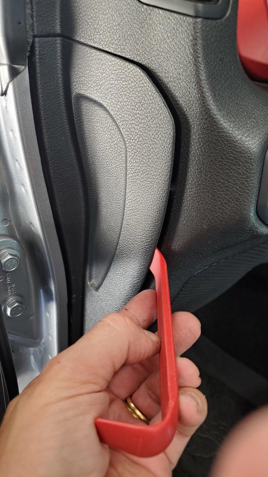
The displayed, partially removed screws below are the only screws that must come out from under these panels, except there is one hidden screw recessed in the side of each Speaker Pod. The recessed screw is accessible within one of those larger silver "holes," and you can access it with a short Phillips head screwdriver. Once again, this applies to both the passenger and driver's side panels.

Then, you'll need to remove the plastic panel under the steering column (body clips - pull the panel directly towards the driver's seat).

On the passenger side, remove the glove box (depress the latch at the top-inside of the glove box to pull it down and outward). Then, remove the three black dash screws under the area where the glove box was. Only the black 7mm screws need to be removed.
On the driver's side, each of the black 7mm screws visible here must be removed.
(Edit: Provided by @onspeed) Another Little tip regarding the driver side speaker pod removal. The metal bar that sits under the pod that causes all the grief is held in by 4, easily accessible bolts; two 10mm and two 8mm. Remove the left most 3 and the bar is able to flex easily out of the way to drop the speaker pod down.
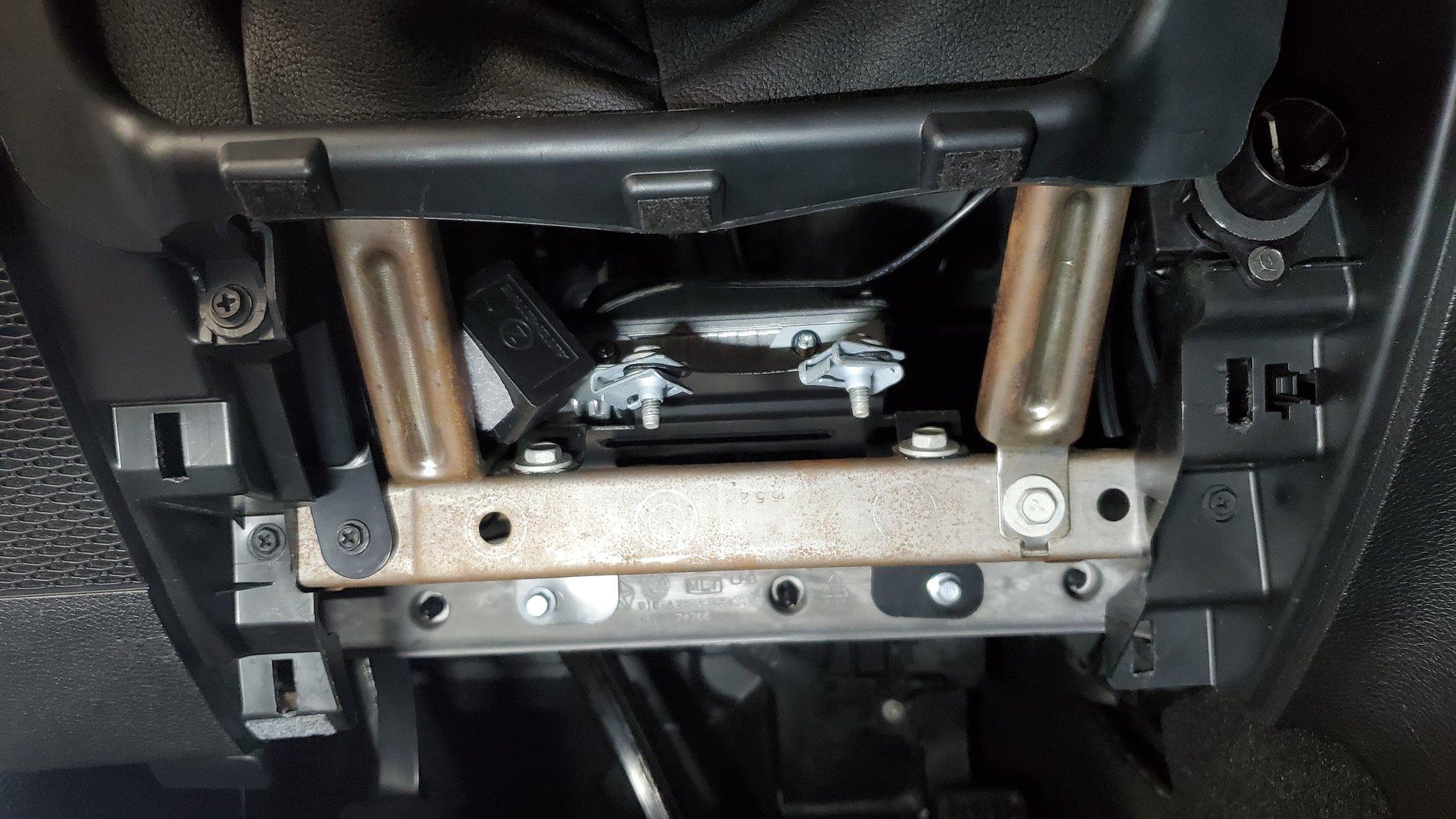
Oh, and don't forget to remove this screw, too. It's tucked in just to the right of the Headlight/Dimmer pod, and removing it will give you much more space when rotating the driver's side Pod out.
As mentioned, each of the Kick Panel speakers have a hidden screw recessed in the side dash panel area, as well as a screw at the top and bottom of the enclosure itself. Once all 3 of each speaker enclosure's screws are removed, you may carefully pull the bottom section of the dash away from it's mounts to access the Pods. Doing so allows you to rotate the speaker enclosures out. Be careful that you don't pull the dash so far out that you crease/pinch the dash covers.
The passenger side Kick Panel Speaker Pod rotates out easily, so there's no additional feedback provided for it. Simply unplug the speaker wire plug on the back, and you're done here!
There are a few NEW tricks to getting the driver's side Pod out easily.
After removing the side dash panel, the panel under the steering wheel and all of the screws previously shown, pop off the cover for the Headlight knob and Dimmer wheels using a pry tool.
Next, from behind the dash, use your fingers to compress the silver tabs on the Headlight Knob/Dimmer plug. This will allow the assembly to easily pop out and provide access to the top Kick Panel Speaker Pod's mounting screw. Two clips on the top, and two clips on the bottom of the Headlight/Dimmer plug allow it to easily be pulled out, and there's no need to disconnect the wires.

Here's the screw location for the top of the Driver's side Pod. Using a magnetic screwdriver will help in removing and re-installing this screw, as it's recessed a bit behind the Headlight/Dimmer pod. You can also use tape to temporarily hold the screw onto the screwdriver when re-installing.
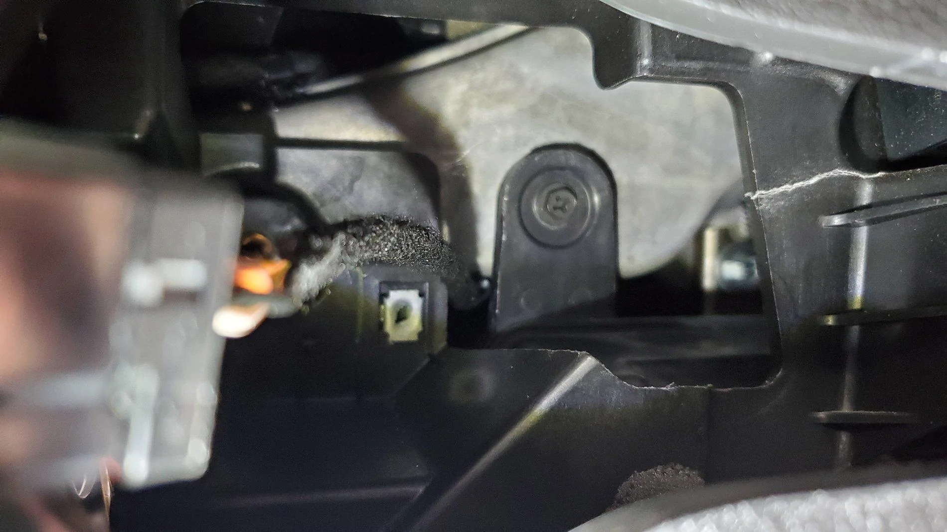
The above photo is from a non-premium system. If you have the premium system, the GPS antenna partially blocks the upper pod speaker screw and taking up space.
(Edit shared by @oceanblue2019) You can remove the GPS antenna by removing the black 7mm/Phillips head screw you see on the bottom metal bracket. From there, remove the pink coax connector and the antenna will come out through the open light-switch hole.
When reassembling:
Make sure the antenna cable is pulled up to the front when you re-install the new Metra Pod, it likes to fall behind the pod and due to it's connector it can not be pulled back over the top without working the pod down again. Install the top pod screw, slide the antenna through the light-switch hole, then connect the antenna connector, and bolt it back in, then connect the light-switch connector back up.
Another tip that makes the Metra's easier -- on the drivers side file down the 3 standoffs for the gateway to get it as close to the pod back as you can. A 1/4" can come off them. Also when you do the 3 bolts up push the gateway as high up on the pod as it will go as the holes to fasten it are quite a bit larger then the screw size. This gets you more clearance to make it easier to get it over the metal lower dash support when going back in.
Once the side, top and bottom pod screws are removed, there's another trick to share regarding the removal of the driver's side Pod.
To do so, pull the dash section's you've loosened outward with your right hand, being careful not to crease any parts of the dash by bending it. Run your left hand up the inside of the dash to guide the top of the Pod. Then, with your right hand on the bottom of the Pod, lift up on the Pod, pushing it up into the dash as far as it will go, then, using your right hand, pull the bottom of the Pod towards you. It will pop over the metal dash frame that's under it, and you'll be able to rotate it out after that. You may need to rock the bottom of the Pod back and forth a few times while lifting up on it.
There's a black box connected to the back of the driver's side speaker with three screws. It's called a Gateway, and it's actually one of the things that makes the driver's side Pod so difficult to remove. You'll need to unplug both of its modular plugs (unless you're already running a Tazer JL) before removing the driver's side Pod.
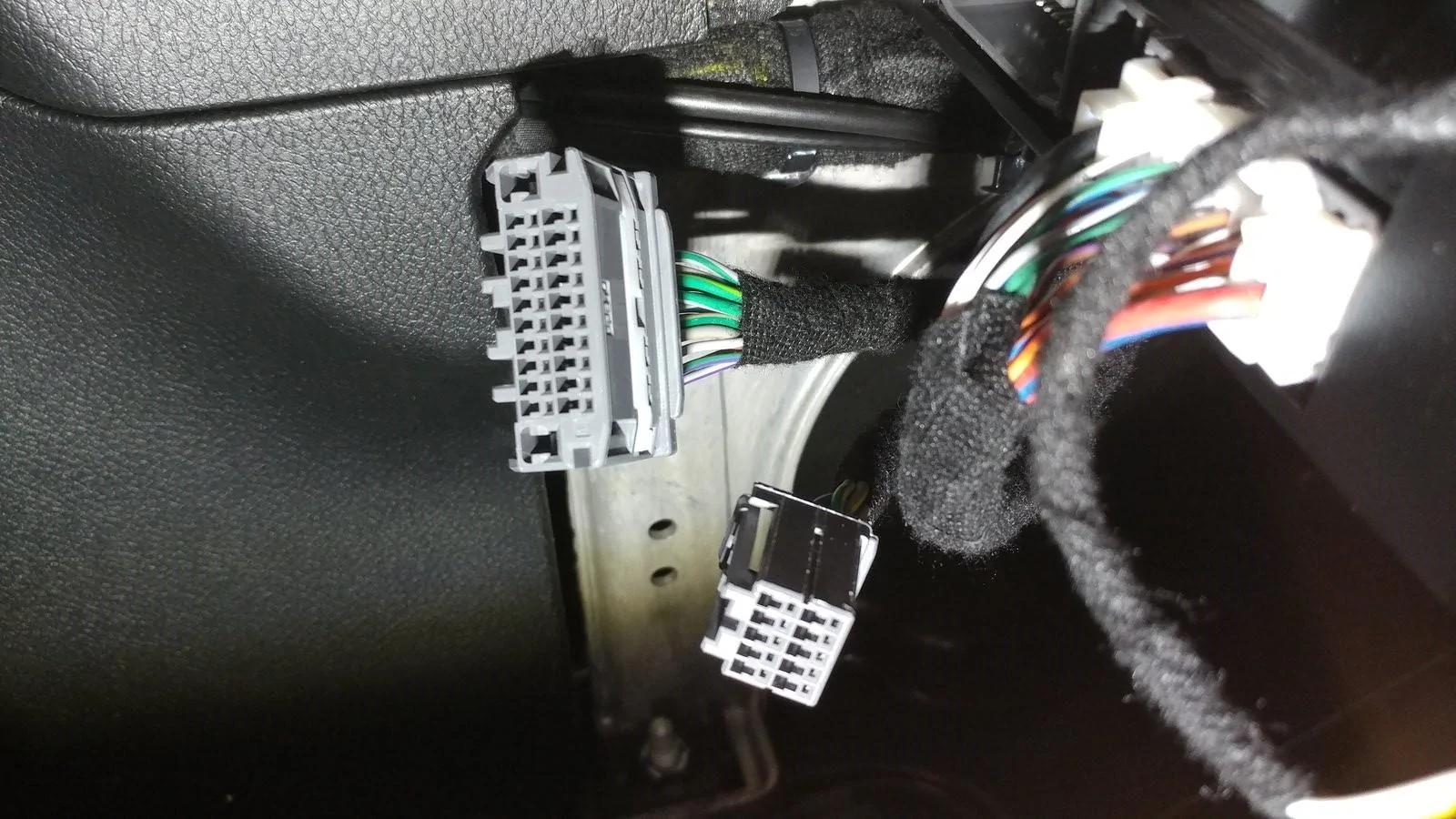
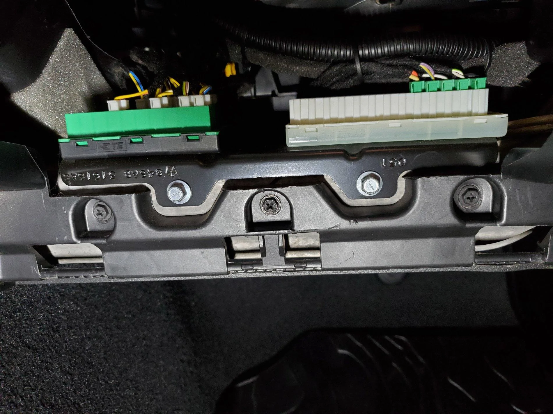
Important: If you re-install your Metra Pods and your stereo doesn't turn on, it's likely because you didn't plug the Gateway's modular plugs back in. (This is the most requested question I receive!) The Gateway is the device in the bottom left of the following picture, and the driver's side Metra Pod has a place for this to be mounted on the back.
There's also a rather large hole on the back of the Metra Pod. The stock Mopar pods you removed have rubber plugs that you'll want to transfer. Just be sure to run your speaker wires through these rubber plugs before adding wire connectors and before trying to re-install the Pods.
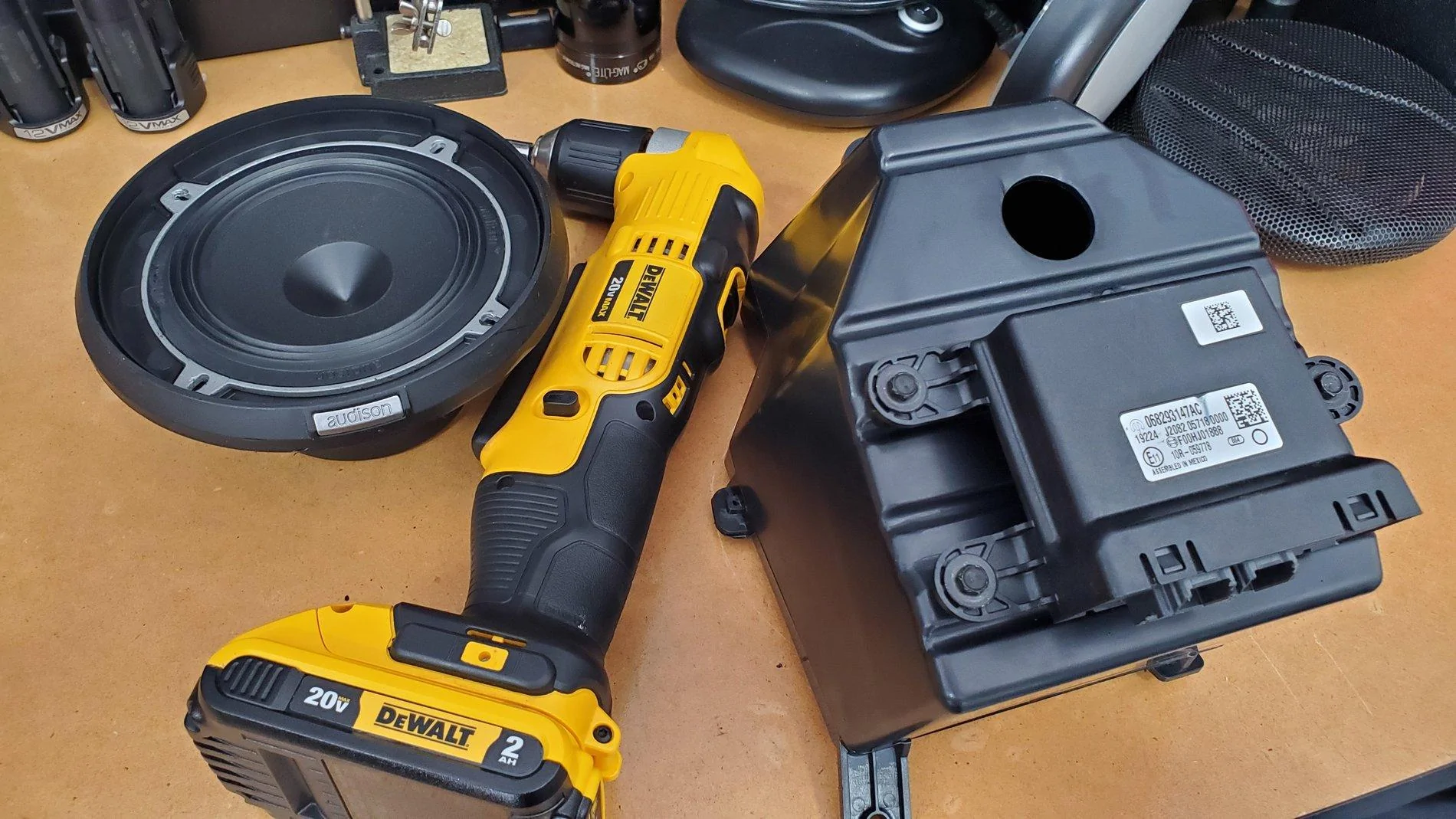
Pictured below is one of the new Metra pods before the speaker's installed and another picture before the finished Pod is ready to be installed.
Note that I'm running 5.25-inch separates, yet these Pods are made for 6.5's. By using the speaker manufacturer's (Audison in this case) provided housing, the housing sits right over the 6.5-inch holes. Also, on the passenger side pod, there will still be a few screw holes open. Make sure you seal each unused hole with silicone, and/or a small screw, or it could end up "whistling."
While not shown, I did add sound deadening material inside the box, polyfil inside the box and also cut a gasket from the sound deadening material that sits between the speaker ring and the Metra Pod. The gasket simply seals out any air from the remaining, unused screw holes under the speaker.
To re-install everything, simply reverse the order above, ensuring all screws, clips and plugs go back nice and easy. There's no need to force anything.
When re-installing the driver's side Pod, you'll benefit by viewing the top bracket through the Headlight/Dimmer portal, ensuring it's at the location shown below before pushing the Pod up as far as it will go. Once you verify it's in the right spot, begin wedging the bottom of the Pod inward towards the front of the car. If you don't have the top section in the right spot, you'll struggle with pushing the Pod upward enough for the bottom and Gateway to clear the metal frame bracket. It really shouldn't require much force.
The Soundbar:
If you do choose to upgrade to larger speakers in the soundbar, modifying the soundbar to accommodate larger speakers is fairly straight-forward. It takes some time/skill with a Dremel tool to enlarge the speaker cavities. You can fit a decent pair of mid-range coaxial speakers up there, or you could choose speaker separates. Each of the rear channels in the sound bar has a mid-range speaker and a separate tweeter already, so separates are possible, you'd just have to wire them on your own. Meaning, the stock mid-range woofer and tweeter on each channel share the same two wires (they aren't discreet). For separates, you would use the wire going into the mid-range woofer to connect to the separates' crossover, then run a new wire from the crossover to the new woofer and new tweeter.
Note, I rate upgrading the Soundbar speakers as "beginner" level install if you stay with 4-inch speakers, and as an "intermediate" level install if you up-size your speakers to 5.25-inch or larger.
Side note: All of the speakers in this system come factory installed in ported enclosures. That's how these little stock speakers sound slightly better than they should.
I have deleted all "concerning" commentary previously shared regarding upgrading the kick panels now that the Metra pods are available. With the Metra pods, we are now presented with such a great option that I can't recommend anything other than using them with 6.5-inch separates. Advice: Invest the majority of your sound system money in the front soundstage, and use the soundbar speakers as nothing else but "fill" speakers.
If, after that advice, you still choose the Resistor route and use the JL Audio Fix™ 86, there is a calibration process necessary that requires a little patience. When calibrating the device, you must be 100% successful in "tricking" all four channels of the uConnect system into turning themselves on. If calibration doesn't work, meaning all channels didn't come on and all 4 lights on the JL Audio Fix™ 86 aren't green during the calibration, you should check your wire connections and possibly your solder points for the resistors. I had one resistor that didn't work initially - it happens.
VERY IMPORTANT: Ensure you are using the JL Fix86's test track for the calibration. JL Audio offers the file as a download. You can't simply copy the file off of the CD. It needs to remain a high-quality source, and you should ensure that sound will play on your system before attempting the calibration process.
Note that, if the JL Audio Fix™ 86 calibration process fails, you have to power down the receiver (key off, and away from the vehicle for about five minutes) until the radio fully resets. You'll know you're successful with the reset if the radio displays the disclaimer screen and boots up as normal. This is due to the fact that once the uConnect system detects a stock speaker isn't there, and the resistor override isn't functioning (for whatever reason), it has to be completely powered down and allowed to reset before uConnect will initiate a new load sensing test. On the plus side, once everything is connected and calibrated, you'll have the cleanest and flattest signal possible from a stock radio. And, you can plug your laptop or phone into the JL Audio FiX™ 86 to tweak the settings and EQ!
As with anything aftermarket, please understand you are taking any install advice provided here into your own hands, and at your own risk. I have to recommend that any power wiring, especially when wiring directly to the battery, be fused at the battery/source. In the case of a short, this blows the fuse instead of creating a new welding source! I also recommend using basic relays for your remote connections, which reduces the risk of feeding power back into your Jeep's electrical system due to a faulty amplifier or component.
Thanks,
Mike
PS: For any jlwranglerforums.com members wanting to venture into upgrading their sound systems, I've arranged a contact that can assist you with purchasing the proper equipment. He'll be happy to advise on gear that fits your needs and budget, and he's agreed to offer discounts to our members if you mention you saw his name here. To get started, contact Travis Grim @ 704-530-2073. He's based near me in the Charlotte, NC area, is a fellow Jeep owner and has approved the sharing of his contact information. All I ask: If you use him as a resource and plan to buy, please buy from him. He's a highly knowledgeable, low pressure manager engaged with a large Charlotte audio/video outfit.
PPS: Don't skimp on your main power wire. There are several types of wire available with the two primary versions being CCA and OFC. Get OFC. It transfers power more efficiently and runs cooler.
______________________________________________________
Base System Speaker Wiring
For those who may also need these color codes, the following is what the schematic provides.
Actual schematic for the Base Radio may be viewed here: https://www.jlwranglerforums.com/JL-Wiring-Diagrams/AUDIO-SYSTEM---BASE.pdf
Left Front Windshield Grey/Violet (+) and Grey/Yellow (-)
Left Front Kick
Right Front Windshield Dark Green/Violet (+) and Dark Green/Yellow (-)
Right Front Kick
Left Rear Sound Bar Grey/Green (+) and Grey/Dark Green (-)
Right Rear Sound Bar Dark Green/Green (+) and Dark Green/Grey (-)
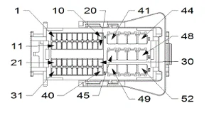
Update: In addition to the above speaker wiring, an image of the radio harness is attached below, and I've added the wiring colors from the back of the base and premium radios.
There is no external amplifier in the base model system. The external amp for the premium system is under the steering column (you should see the color coded wires below).
Speaker wire colors at the radio, with pin number and polarity:
Base Radio
PIN Wire Speaker/Polarity System
45 DG/GN RIGHT REAR SPEAKER (+) BASE RADIO
46 DG/VT RIGHT FRONT SPEAKER (+) BASE RADIO
47 GY/VT LEFT FRONT SPEAKER (+) BASE RADIO
48 GY/GN LEFT REAR SPEAKER (+) BASE RADIO
49 DG/GY RIGHT REAR SPEAKER (-) BASE RADIO
50 DG/YE RIGHT FRONT SPEAKER (-) BASE RADIO
51 GY/YE LEFT FRONT SPEAKER (-) BASE RADIO
52 GY/DG LEFT REAR SPEAKER (-) BASE RADIO
Premium Radio
Actual schematic for the Premium Radio may be viewed here here: https://www.jlwranglerforums.com/JL-Wiring-Diagrams/AUDIO-SYSTEM---PREMIUM.pdf
45 GY/DB RIGHT REAR SPEAKER (+) PREMIUM RADIO
46 GY RADIO RIGHT FRONT AUDIO (+) PREMIUM RADIO
47 DG RADIO LEFT FRONT AUDIO (+) PREMIUM RADIO
48 DG/DB LEFT REAR SPEAKER (+) PREMIUM RADIO
49 GY/OG RIGHT REAR SPEAKER (-) PREMIUM RADIO
50 GY/BN RADIO RIGHT FRONT AUDIO (-) PREMIUM RADIO
51 DG/BN RADIO LEFT FRONT AUDIO (-) PREMIUM RADIO
52 DG/OG LEFT REAR SPEAKER (-) PREMIUM RADIO
Sponsored
Last edited:

