CarbonSteel
Well-Known Member
- Thread starter
- #1
The installation took about 3.5 hours from start to finish. I did not rush, and everything went very smoothly. Make sure that you get new fender clips--you will need them. Nine out of ten of mine broke and I since I will be replacing both batteries soon and the other fender will have to be removed as well, I picked up a forty pack of them on ebay.
The only thing that I forgot to do was install the "keeper" on the main power wiring, so make a note to do that—BEFORE you re-install the fender because you will not be able to reach it afterwards. I do not think mine will disconnect, but if it does, it will require pulling the fender again. I also elected not to remove the driver’s front tire and I am good with that decision. Removing it does not make the installation any easier because there is plenty of room to do what is needed.
Tools/Parts Needed:
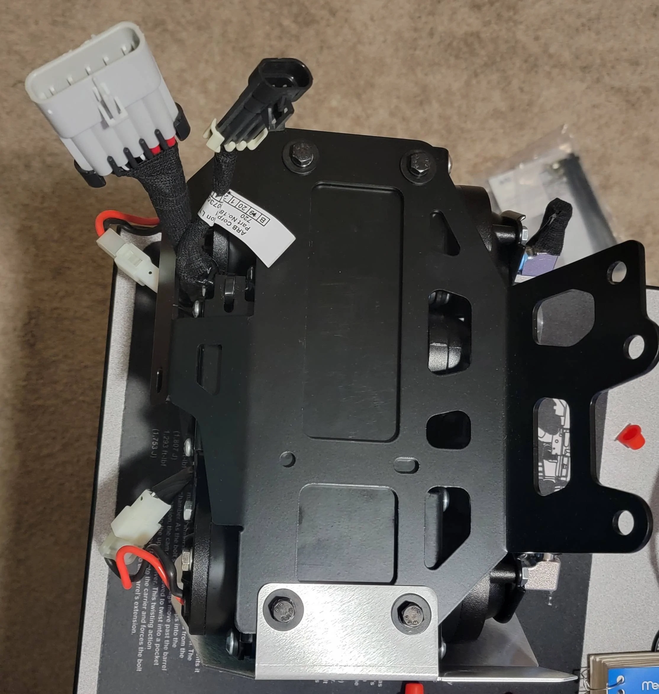
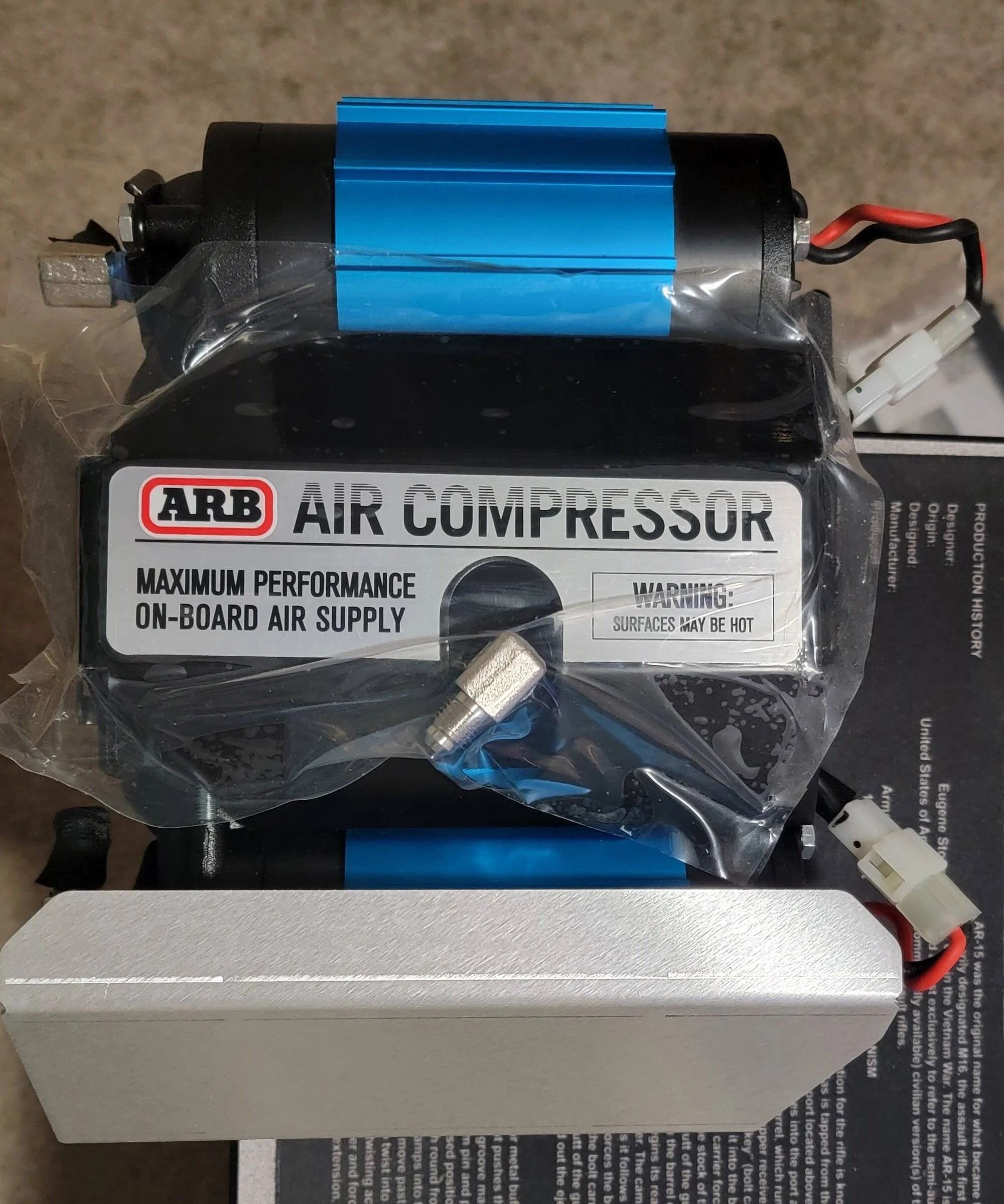
Step 1 - Mount the air compressor into the Grimm mount. Be sure to use blue loctite on the screws to prevent loosening in the future.

Step 2 - Install the air intake ferrules as well as the high-pressure outlet connection on the compressor. I wrapped the intake ferrules with electrical tape to prevent dirt from entering during the installation and lifted the protective plastic wrap and used it to cover the high-pressure outlet as well.

Step 3 - Assemble the air chuck and air inlet filters onto the Grimm mounting plate. Be sure not to overtighten ferrules on the plastic air filters as they will strip or break.

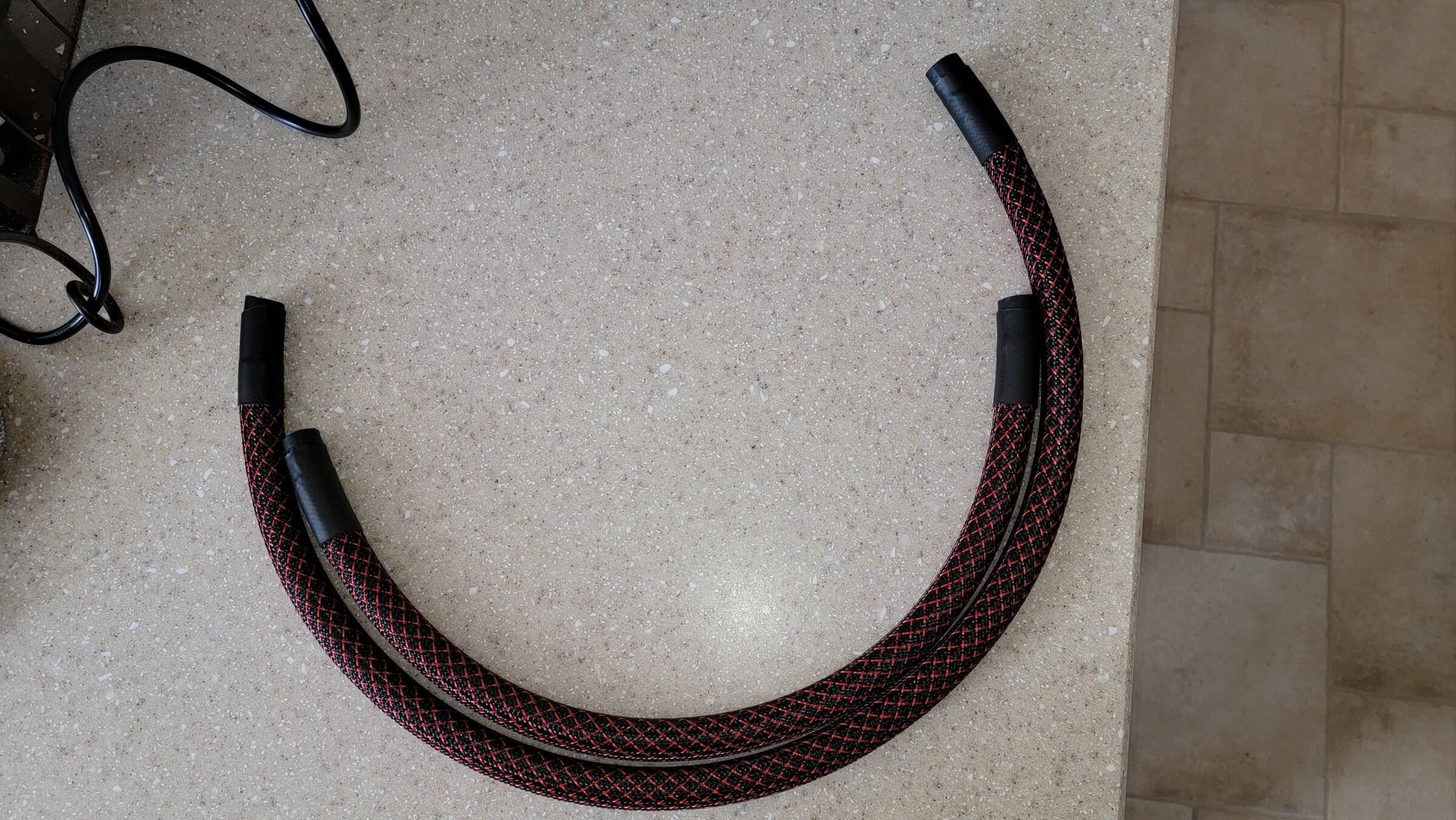
Step 4 - (not really required) I installed PET braided tubing and applied heat shrink tubing on the ends to prevent fraying to give an extra layer of protection.
Step 5 – Remove the Christmas tree retainer and the five 10mm bolts from the fender.
Step 6 – Pull on the fender to detach it from the body. It takes some force and you should start on one end or the other. DO NOT pull it too far away from the body because there is a wiring harness for the turn signals/park lights that has to be disconnected.
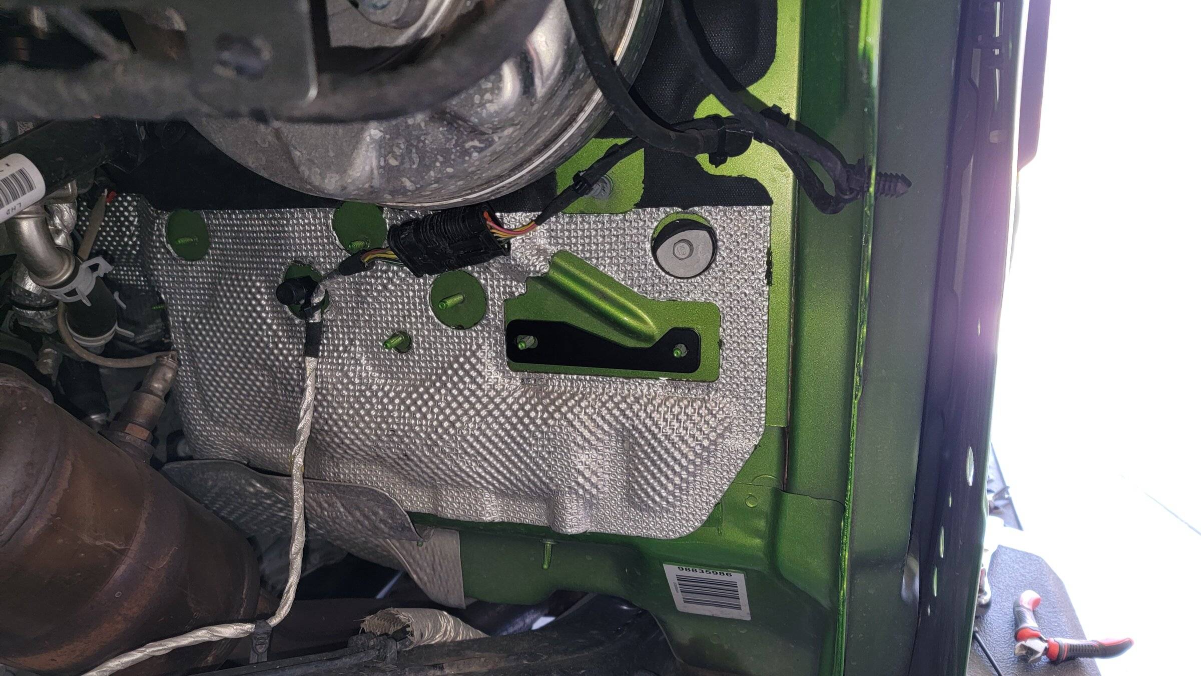
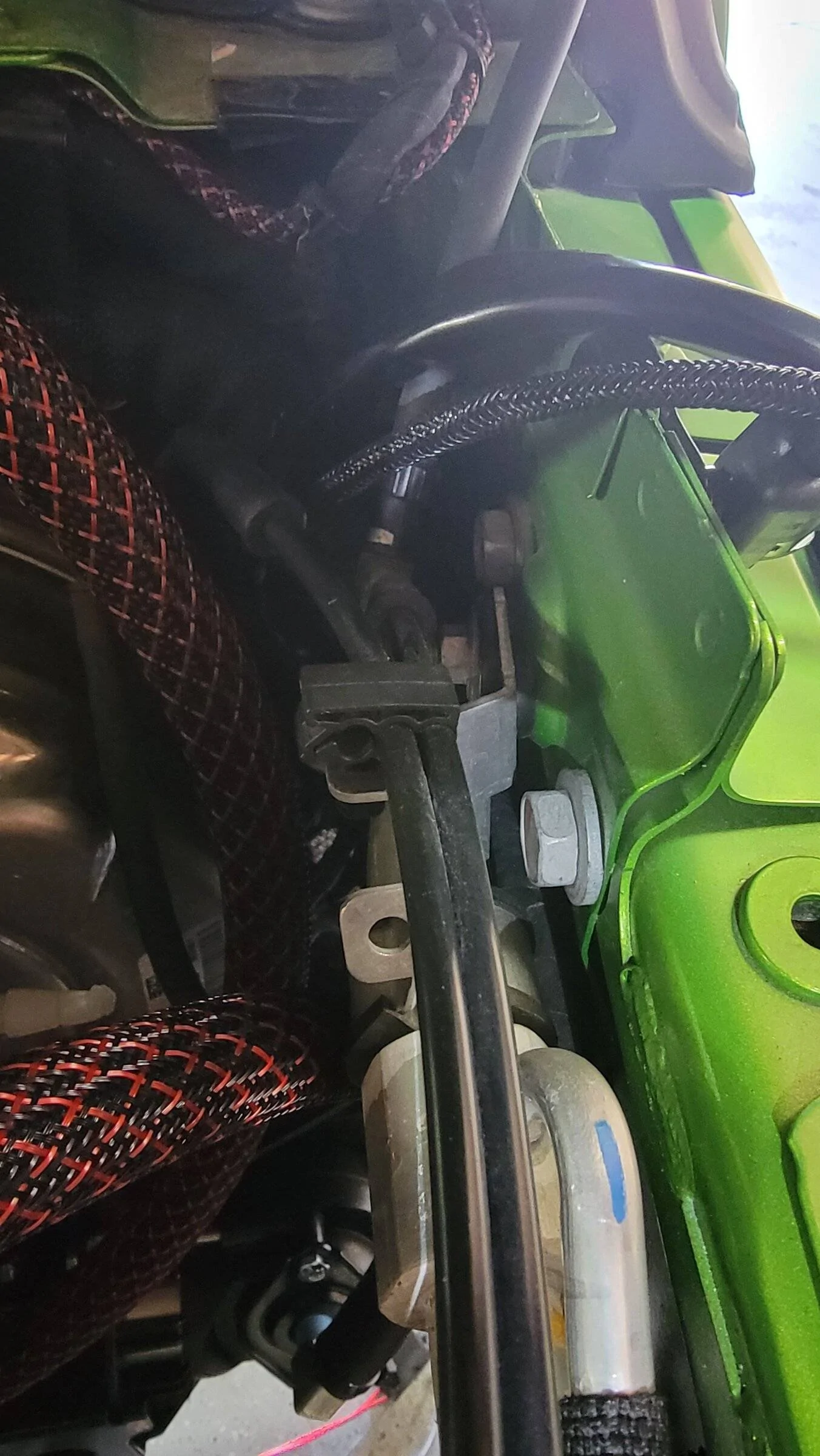
Step 7 - Remove the two 10mm nuts and the wiring bracket from the firewall and detach the wiring from it. There is a "Christmas tree" connector on the wiring that also has to be disconnected from the fender. Cut the original zip tie from the gray post connector and use a new one to re-attach the wiring to it. I also added zip ties in two other locations to secure the wiring but it is not necessary. Add the Grimm Spacer to the studs on the firewall. Next, remove the 13mm nut from the lower master brake cylinder stud.
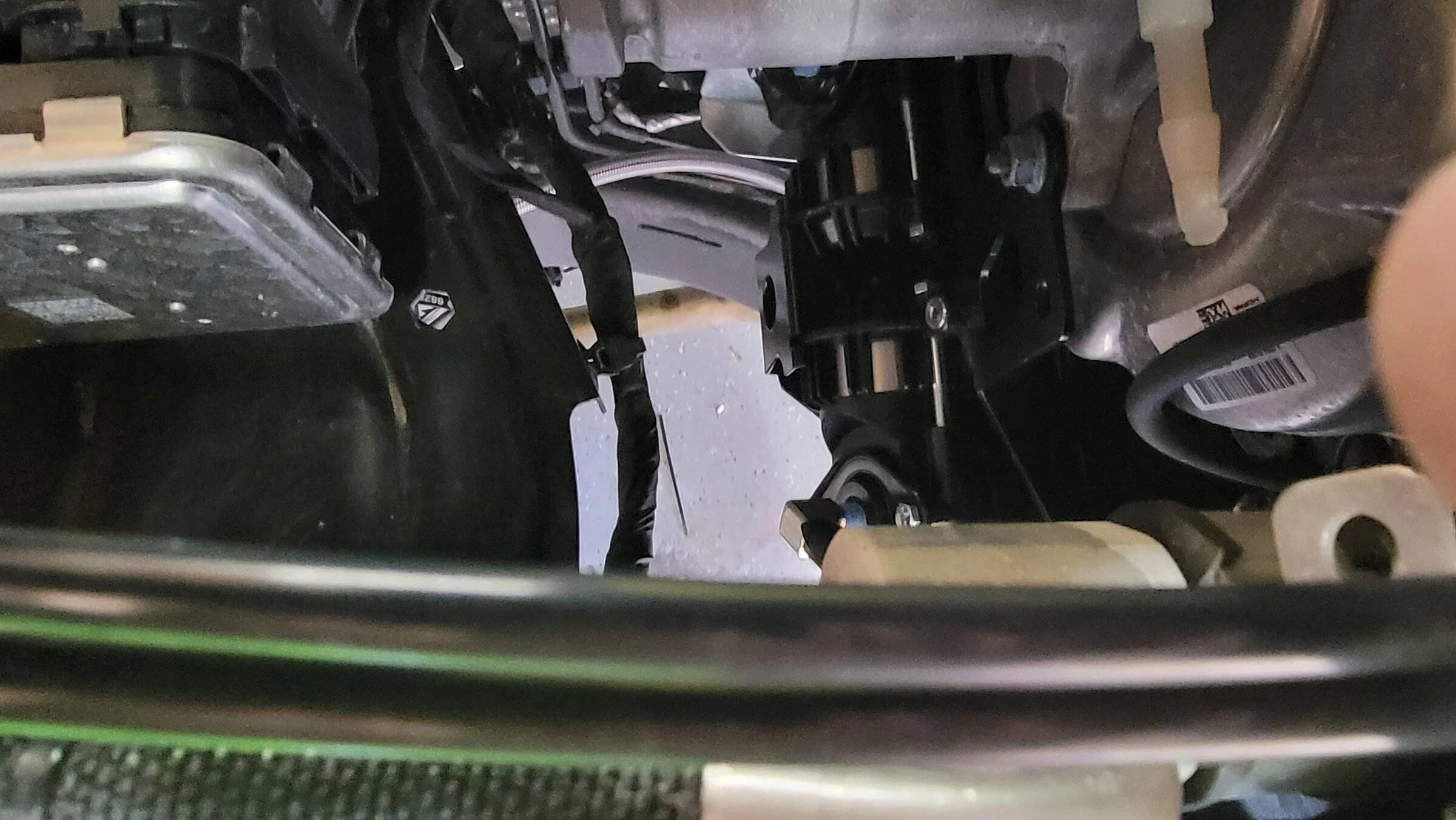
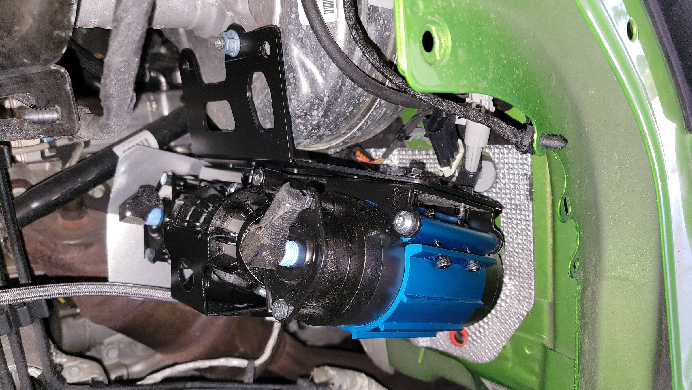
Step 8 – Mount the compressor onto the two firewall studs and the stud on the master cylinder. Reinstall the 10mm nuts on the firewall. A 10mm combination wrench will be needed to tighten them. Next re-install the 13mm nut onto the master cylinder bracket and tighten.
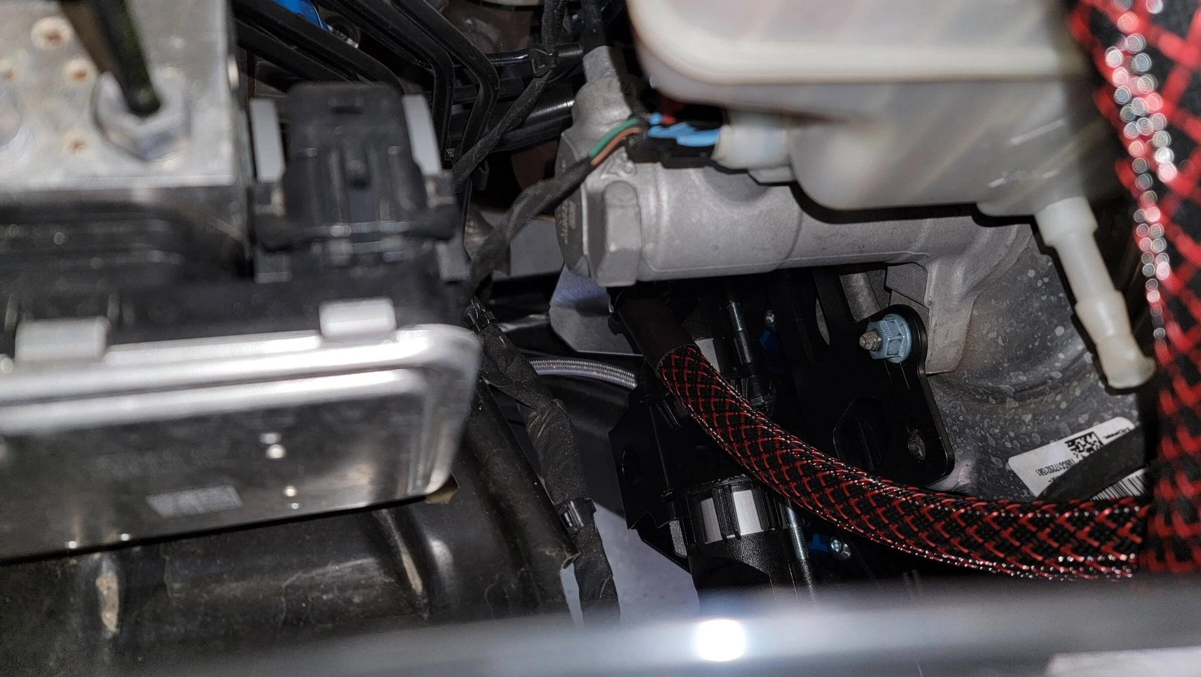
Step 9 – Attach the air intake hoses, the high-pressure stainless braided hose, the ARB power cable, and the Grimm switch cable and route them to their approximate locations. Be sure to use some di-electric grease on the connections to prevent the inevitable corrosion that will happen if left untreated.

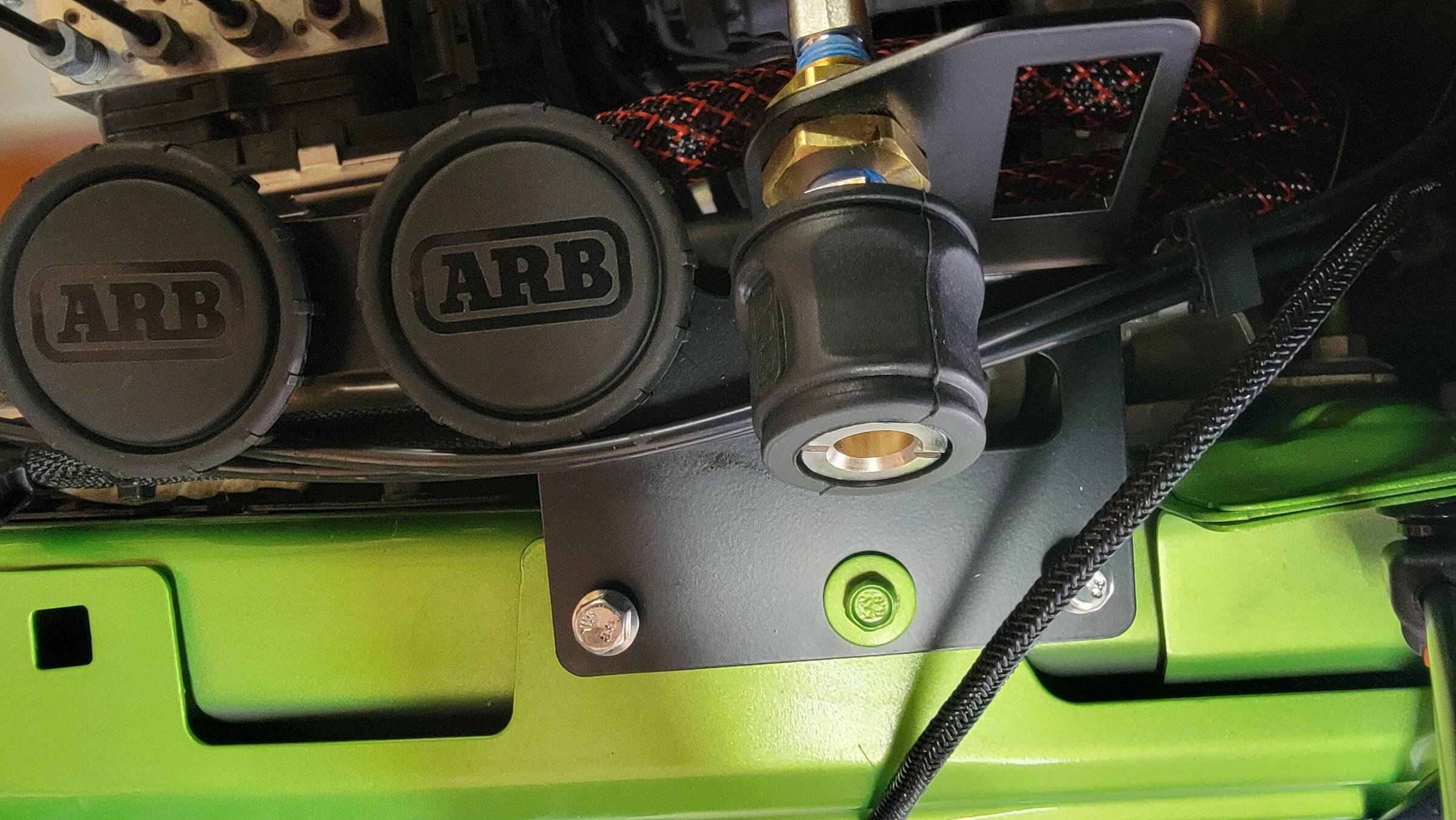
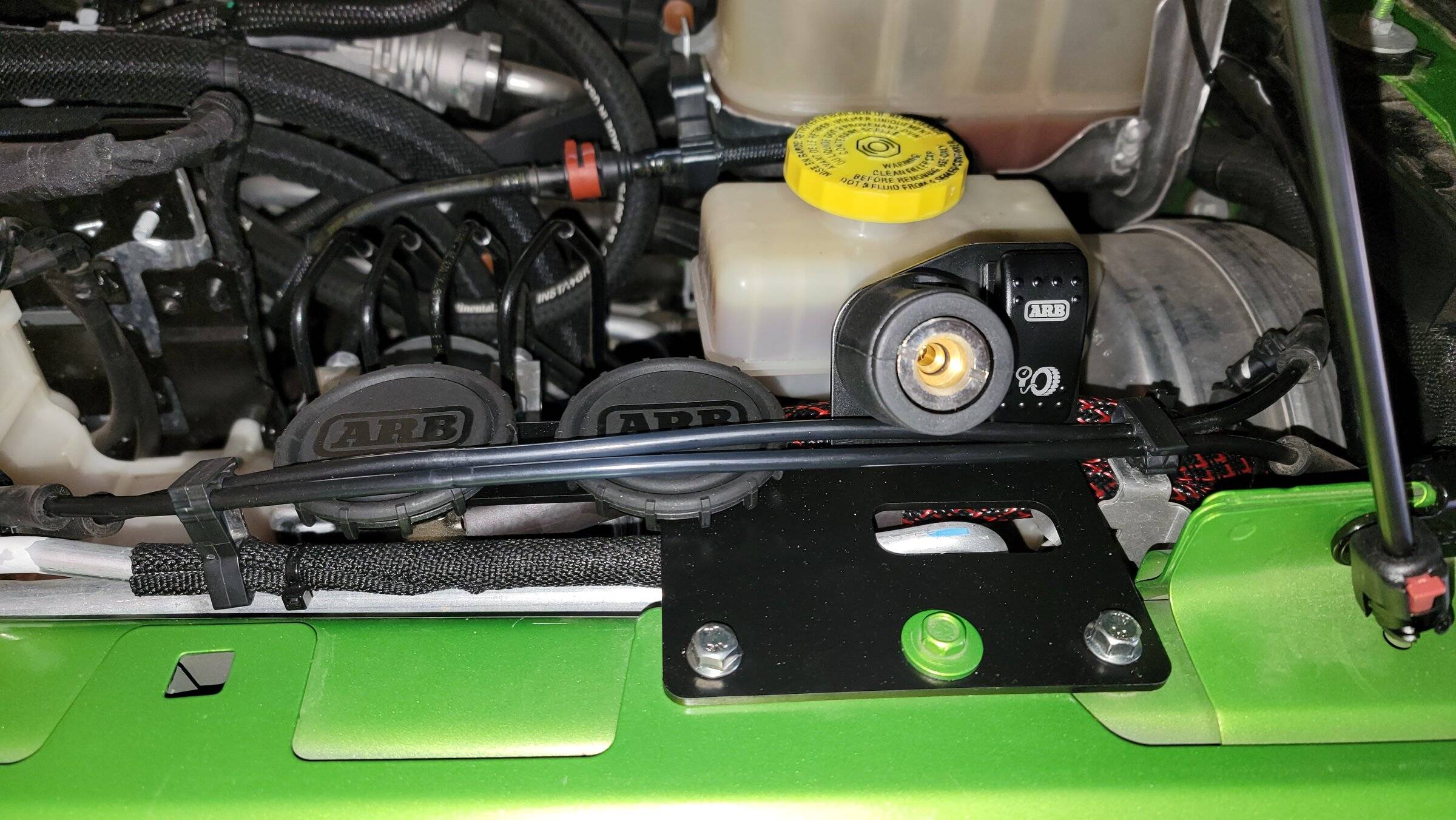
Step 10 – Mount the Grimm switch and air chuck plate in its location and attach the air intake hoses and the high-pressure stainless steel hose. Pass the Grimm switch wiring through the hole on the plate. Ensure the arrow on the back of the switch is pointing up. The connections used will be the side with the 3 spade connectors. Connect the purple wire to the bottom blade, the red to the center, and the black to the top blade. Snap the switch into place.
Step 11 – Route the ARB power cables behind the engine over to the battery. I used zip ties to secure the harness to the cowl wiring trough mounts pulling it snug as I tied them. I then crimped on some 8 gauge 5/16” ring terminals to each of the positive wires and applied some red heat shrink tubing to further insulate them.
Step 12 – Twist the small black wire from the ARB power cable onto the 8 gauge black wire and crimp an 8 gauge 5/16” ring terminal (both wires go into the one ring terminal. I then applied some black heat shrink tubing to further insulate the wire.
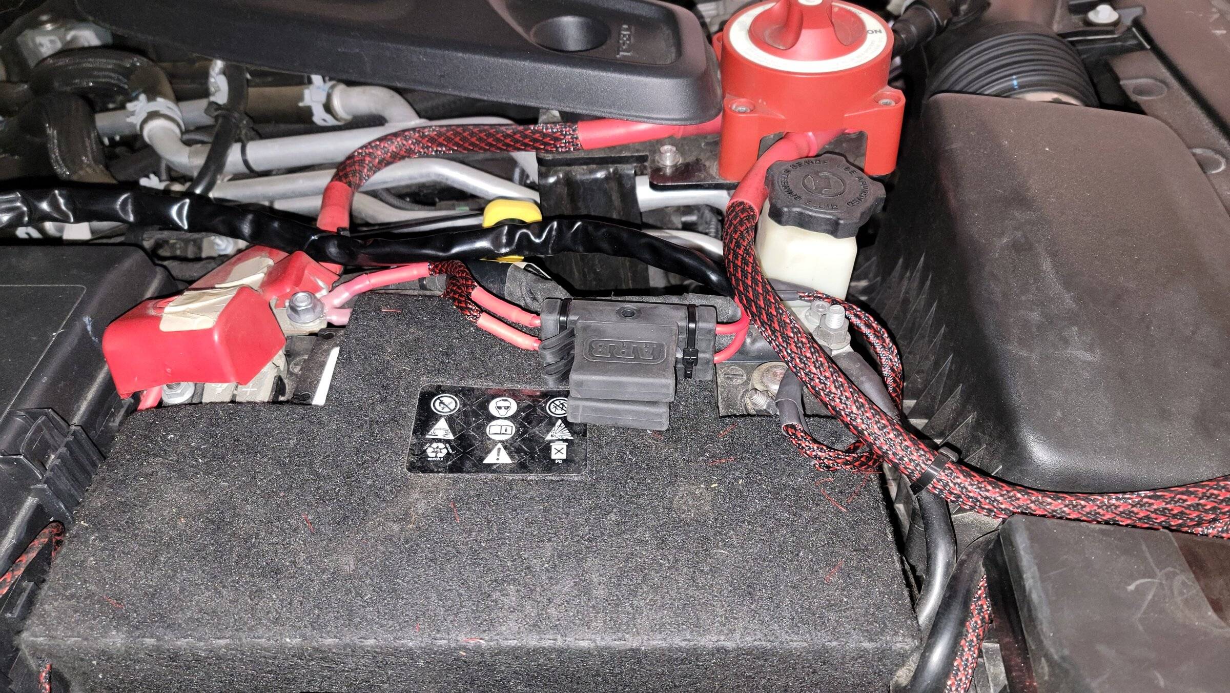
Step 13 – Remove the fuses from the ARB fuse holder and add some di-electric grease to the terminals inside the fuse holder. Reinstall the fuses ensuring they are firmly seated. Replace the weather resistant caps on the fuse holder ensuring they are properly seated.
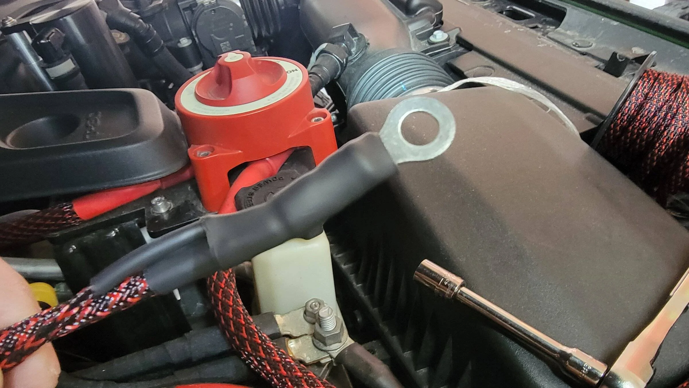
Step 14 - Remove one of the nuts on the positive terminal block on the battery, attach the red wires. Replace the nut and tighten. Repeat this process for the black wire on the negative terminal block. Arrange the wiring and secure as necessary with additional zip ties.
Step 15 – Test the compressor to ensure it operates properly. Arrange any remaining wiring as needed and secure with zip ties.
Step 16 – Replace all of the broken fender clips on the fender. I found the easiest way to remove them is by breaking off the flat tab on each edge of the clip, then slightly rotating them to remove from the fender. Reinstall new tabs ensure they are fully seated and lie flat against the fender.
Step 17 – Loosely place the fender in its location and re-attach the turn signal/parking light wiring. Make sure the fender cannot fall and test your lights to be sure both are working BEFORE attempting to re-attach the fender. After testing, place the fender in its location and push on it in a straight line towards the passenger side. The lower part of the fender will likely not pop back into place requiring you to push fairly hard on it.
Step 18 – Replace the five 10mm bolts and tighten. Next replace the Christmas tree retainer.
Step 19 – Double check your work and clean-up your work area
Step 20 – Go wheeling knowing that you can now air up and down as needed on the trail.
Thanks @Grimm OffRoad!
The only thing that I forgot to do was install the "keeper" on the main power wiring, so make a note to do that—BEFORE you re-install the fender because you will not be able to reach it afterwards. I do not think mine will disconnect, but if it does, it will require pulling the fender again. I also elected not to remove the driver’s front tire and I am good with that decision. Removing it does not make the installation any easier because there is plenty of room to do what is needed.
Tools/Parts Needed:
- 10mm Combination Wrench
- 10mm Socket and Ratchet
- 12mm Socket and Ratchet
- 13mm Combination Wrench
- 13mm Socket and Ratchet
- 15mm Combination Wrench
- Zip Ties
- PET Braided Wire Covering (optional)
- Heat Shrink Tubing (optional)
- Heat Shrink 8 Gauge 5/16" Ring Terminals
- Teflon Tape
- Blue Loctite
- Di-Electric Grease
- Fender Clips (it takes 10 per fender, but you may get lucky on some) (https://www.ebay.com/itm/293957627093)
Step 1 - Mount the air compressor into the Grimm mount. Be sure to use blue loctite on the screws to prevent loosening in the future.
Step 2 - Install the air intake ferrules as well as the high-pressure outlet connection on the compressor. I wrapped the intake ferrules with electrical tape to prevent dirt from entering during the installation and lifted the protective plastic wrap and used it to cover the high-pressure outlet as well.
Step 3 - Assemble the air chuck and air inlet filters onto the Grimm mounting plate. Be sure not to overtighten ferrules on the plastic air filters as they will strip or break.

Step 4 - (not really required) I installed PET braided tubing and applied heat shrink tubing on the ends to prevent fraying to give an extra layer of protection.
Step 5 – Remove the Christmas tree retainer and the five 10mm bolts from the fender.
Step 6 – Pull on the fender to detach it from the body. It takes some force and you should start on one end or the other. DO NOT pull it too far away from the body because there is a wiring harness for the turn signals/park lights that has to be disconnected.
Step 7 - Remove the two 10mm nuts and the wiring bracket from the firewall and detach the wiring from it. There is a "Christmas tree" connector on the wiring that also has to be disconnected from the fender. Cut the original zip tie from the gray post connector and use a new one to re-attach the wiring to it. I also added zip ties in two other locations to secure the wiring but it is not necessary. Add the Grimm Spacer to the studs on the firewall. Next, remove the 13mm nut from the lower master brake cylinder stud.
Step 8 – Mount the compressor onto the two firewall studs and the stud on the master cylinder. Reinstall the 10mm nuts on the firewall. A 10mm combination wrench will be needed to tighten them. Next re-install the 13mm nut onto the master cylinder bracket and tighten.
Step 9 – Attach the air intake hoses, the high-pressure stainless braided hose, the ARB power cable, and the Grimm switch cable and route them to their approximate locations. Be sure to use some di-electric grease on the connections to prevent the inevitable corrosion that will happen if left untreated.
Step 10 – Mount the Grimm switch and air chuck plate in its location and attach the air intake hoses and the high-pressure stainless steel hose. Pass the Grimm switch wiring through the hole on the plate. Ensure the arrow on the back of the switch is pointing up. The connections used will be the side with the 3 spade connectors. Connect the purple wire to the bottom blade, the red to the center, and the black to the top blade. Snap the switch into place.
Step 11 – Route the ARB power cables behind the engine over to the battery. I used zip ties to secure the harness to the cowl wiring trough mounts pulling it snug as I tied them. I then crimped on some 8 gauge 5/16” ring terminals to each of the positive wires and applied some red heat shrink tubing to further insulate them.
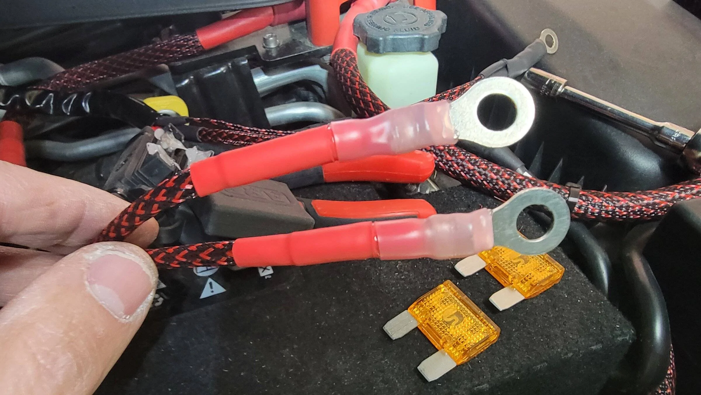
Step 12 – Twist the small black wire from the ARB power cable onto the 8 gauge black wire and crimp an 8 gauge 5/16” ring terminal (both wires go into the one ring terminal. I then applied some black heat shrink tubing to further insulate the wire.
Step 13 – Remove the fuses from the ARB fuse holder and add some di-electric grease to the terminals inside the fuse holder. Reinstall the fuses ensuring they are firmly seated. Replace the weather resistant caps on the fuse holder ensuring they are properly seated.
Step 14 - Remove one of the nuts on the positive terminal block on the battery, attach the red wires. Replace the nut and tighten. Repeat this process for the black wire on the negative terminal block. Arrange the wiring and secure as necessary with additional zip ties.
Step 15 – Test the compressor to ensure it operates properly. Arrange any remaining wiring as needed and secure with zip ties.
Step 16 – Replace all of the broken fender clips on the fender. I found the easiest way to remove them is by breaking off the flat tab on each edge of the clip, then slightly rotating them to remove from the fender. Reinstall new tabs ensure they are fully seated and lie flat against the fender.
Step 17 – Loosely place the fender in its location and re-attach the turn signal/parking light wiring. Make sure the fender cannot fall and test your lights to be sure both are working BEFORE attempting to re-attach the fender. After testing, place the fender in its location and push on it in a straight line towards the passenger side. The lower part of the fender will likely not pop back into place requiring you to push fairly hard on it.
Step 18 – Replace the five 10mm bolts and tighten. Next replace the Christmas tree retainer.
Step 19 – Double check your work and clean-up your work area
Step 20 – Go wheeling knowing that you can now air up and down as needed on the trail.
Thanks @Grimm OffRoad!
Sponsored
Last edited: